Fluid supply valve

Inactive Publication Date: 2001-12-13
SEIKO EPSON CORP
View PDF0 Cites 0 Cited by
  • Summary
  • Abstract
  • Description
  • Claims
  • Application Information

AI Technical Summary

Problems solved by technology

The aforesaid method in which the ink tank inside is almost entirely filled with an absorbent involves the problems that the negative pressure of the absorbent increases accompanying the consumption of the ink, and increases the amount of the ink remaining in the ink tank without being supplied to the recording head, thereby bringing about a low utilization efficiency of the ink.
In general, however, a serious problem with the aforesaid constitution remains unsolved in that the umbrella check valve has an offset value which is too high to precisely regulate the amount of the ink to be supplied to the recording head, thus bringing about unfavorable variation in the amount of the ink to be supplied and consequent deterioration of the quality of the printed letters.
There are also problems that in the state of the umbrella check valve being opened, the recording head is completely isolated from the ink reservoir, which increases the pressure in the cavity, destroys the seal at the connection to the recording head, and thereby causes ink leakage when the ink in the cavity is volumetrically expanded by 2 to 5%, approx. owing to the variation in the environmental temperature; and that in the state of the ink tank being mounted on the recording head, the increased pressure as mentioned above is applied as such to the recording head, which makes it impossible to maintain a negative pressure between the recording head and the ink tank, and thereby causes ink leakage through the recording head.
There is further a problem that since the umbrella check valve is not imparted with a sufficient valve opening power by several tens millimeter of water column that is to be maintained for the purpose of stably supplying the recording head with the ink, there is a fear that the valve is opened in response to the swing of the ink caused by the movement of a carriage, thereby bringing about inferior stability of the printed letters.
However, the disc-shaped valve body to be used in a conventional ink tank valve, which usually has the structure as shown in FIG. 2, and a wall thickness of 0.4 mm, approximately, has involved such problems that the reaction force is not necessarily weak in the case of the deformation of the disc shaped valve body and at the same time, the supply of the ink can not sufficiently follow the amount of the ink which is discharged from the recording head, and the like problems.

Method used


Image

  • Fluid supply valve
  • Fluid supply valve
  • Fluid supply valve

Examples


preparation example 1

[0068] There was prepared an elastic material to be used for producing disc shaped valve bodies in the following manner. Specifically, an elastic material was prepared by sufficiently kneading 100 parts by weight or styrene-ethylene / propylene styrene triblock copolymer (SEPS) {number-average molecular weight of 100,000, solubility parameter (SP value) of 8.5}, 150 parts by weight of paraffin base oil {produced by Idemitsu Kosan Co., Ltd. under the trade name "PW 380", weight average molecular weight of 750, solubility parameter (SP value) of 7.8} and 13 parts by weight of polypropylene resin. The elastic material thus prepared had a hardness of 20 as measured in accordance with JIS K 6301(JIS: Japanese Industrial Standard).

example 1

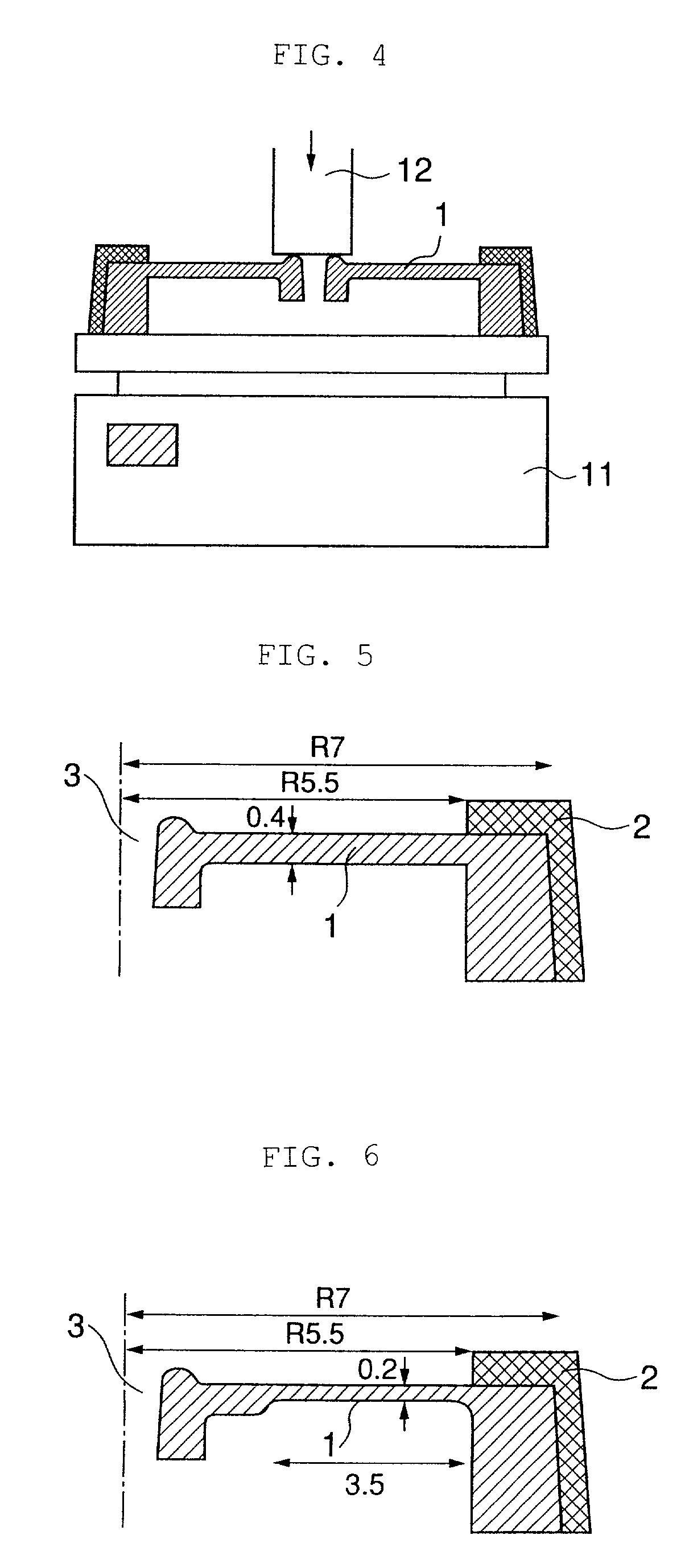
[0070] By the use of the elastic material as obtained in the preceding Preparation Example 1 and polypropylene resin and by two color molding method, there was prepared a disc shaped valve body which had the cross sectional shape as indicated in FIG. 6 (a half cross sectional shape) a fluid supply port 3 installed at the center thereof and a wide thin walled portion having a width of 3.5 mm and a thickness of 0.2 mm along the circumferential direction, and the peripheral portion of which was reinforced with and fixed to a rigid material comprising polypropylene resin 2. Thus, there was obtained the relationship between the displacement and the reaction force of the resultant disc shaped valve body. The results are given in Table 1.

example 2

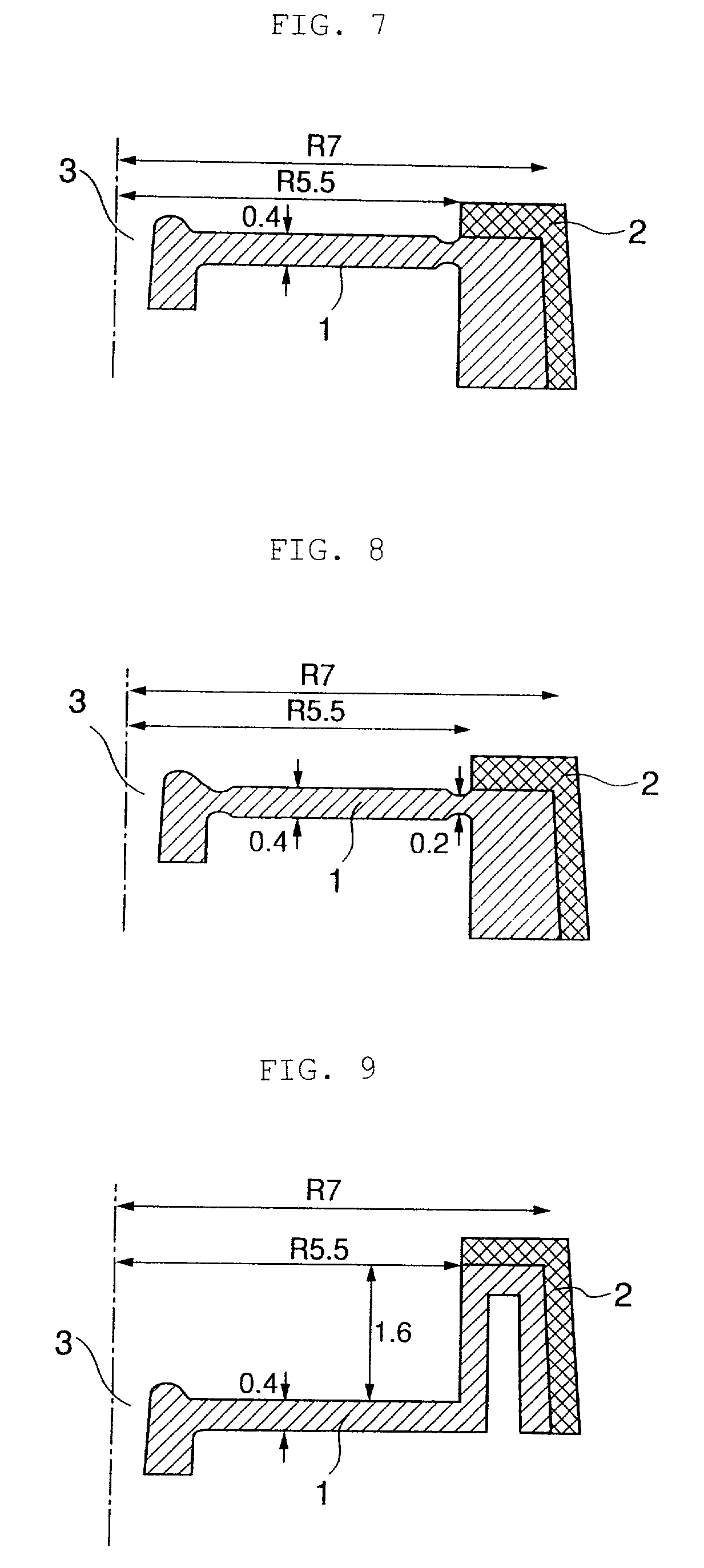
[0071] By the use of the elastic material as obtained in the preceding Preparation Example 1 and polypropylene resin and by two-color molding method, there was prepared a disc-shaped valve body which had the cross-sectional shape as indicated in FIG. 7 (a half cross-sectional shape), a fluid supply port 3 installed at the center thereof and a thin-walled portion having a width of 0.5 mm and a thickness of 0.2 mmm in the vicinity of the peripheral portion along the circumferential direction, and the peripheral portion of which was reinforced with and fixed to a rigid material comprising polypropylene resin 2. Thus, there was obtained the relationship between the displacement and the reaction force of the resultant disc shaped valve body. The results are given in Table 1.


PUM


Abstract

There is disclosed a fluid supply valve comprising a disc-shaped valve body which is equipped with a fluid supply port in the central portion thereof and composed of an elastic material whose peripheral portion is reinforced and fixed with a rigid material, the fluid supply port being closed when the valve body abuts against a fixed valve seat placed so as to be opposite to the fluid supply port, and being opened when the valve body is separated from the fixed valve seat, wherein the disc shaped valve body is equipped further with a thin walled portion in the intermediate annular portion between the fluid supply port and the peripheral portion in the radial direction, and / or with an inflectional portion in the radial direction between the fluid supply port and the peripheral portion. According to the above constitution, it is made possible to minimize the reaction force at the time of the deformation of the valve body and thus to provide an ink tank valve capable of favorably supplying a recording head with a proper amount of ink.

Description

[0001] 1. Field of the Invention[0002] The present invention relates to a fluid supply valve. More particularly, the present invention is concerned with a fluid supply valve which is well suited as an ink tank valve particularly in an ink jet recording apparatus for the purpose of favorably supplying a recording head portion from an ink chamber with an ink in an amount corresponding to the amount of an ink which is discharged from said recording head portion at the time of recording.[0003] 2. Description of the Related Arts[0004] An ink jet recording apparatus has heretofore been equipped with an ink tank which has an ink chamber to be filled in with an ink and also an ink supply portion which supplies a recording head portion with an ink. Examples of types of the ink tanks include a type which is constituted so that an ink is supplied to a recording head which is stationarily attached to a carriage, through tubes arranged everywhere in an ink jet recording apparatus, and an ink tan...

Claims


Application Information

Patent Timeline
IPC IPC(8): B41J2/175F16K15/14
CPCB41J2/17596F16K15/144Y10T137/7888
Inventor KIKUCHI, HIROFUMINISHIMURO, YOUICHIMACHIDA, KUNIO
Owner SEIKO EPSON CORP
Why Eureka
Try Eureka