Intravascular stent device

a stent and vascular technology, applied in the field of stent devices, can solve problems such as hemorrhage in the vessel

Inactive Publication Date: 2007-03-27
CODMAN & SHURTLEFF INC
View PDF102 Cites 125 Cited by
  • Summary
  • Abstract
  • Description
  • Claims
  • Application Information

AI Technical Summary

Benefits of technology

[0012]In accordance with yet another aspect of the present invention, there is provided a self-expanding stent, or aneurysm cover, which takes the form of a small diameter, thin-walled, skeletal tubular member. The wall of the skeletal tubular member comprises a plurality of cells formed by a plurality of interconnected sinusoidal members. The interconnected sinusoidal members are generally parallel to the longitudinal axis of the skeletal tubular member and are generally parallel to each other. Each sinusoidal member has a plurality of positive and negative peaks. The positive peaks of each sinusoidal member are directly connected to the negative peaks of an adjacent sinusoidal member so as to form a repeating cell pattern along the skeletal tubular member. The stent also includes a plurality of junctions formed at the distal and proximal ends of the skeletal tubular member. Each junction occurs at a location where a positive peak of a sinusoidal member is directly connected to a negative peak of an adjacent sinusoidal member. Longitudinal leg members extend from four of the junctions at the distal end of the skeletal tubular member and from two of the junctions at the proximal end of the skeletal tubular member. Each of the longitudinal leg members extends in a direction parallel to the longitudinal axis of the skeletal tubular member. A helically wound radiopaque coil is disposed about each longitudinal leg member and serves as a radiopaque marker for the stent.

Problems solved by technology

Another serious vascular defect is an area of weakened vessel wall that causes a bulge, or bubble, to protrude out in a radial direction from the vessel.
If untreated, the aneurysm may continue expanding until it bursts thereby causing hemorrhaging from the vessel.

Method used


Image

  • Intravascular stent device
  • Intravascular stent device
  • Intravascular stent device

Examples


Embodiment Construction

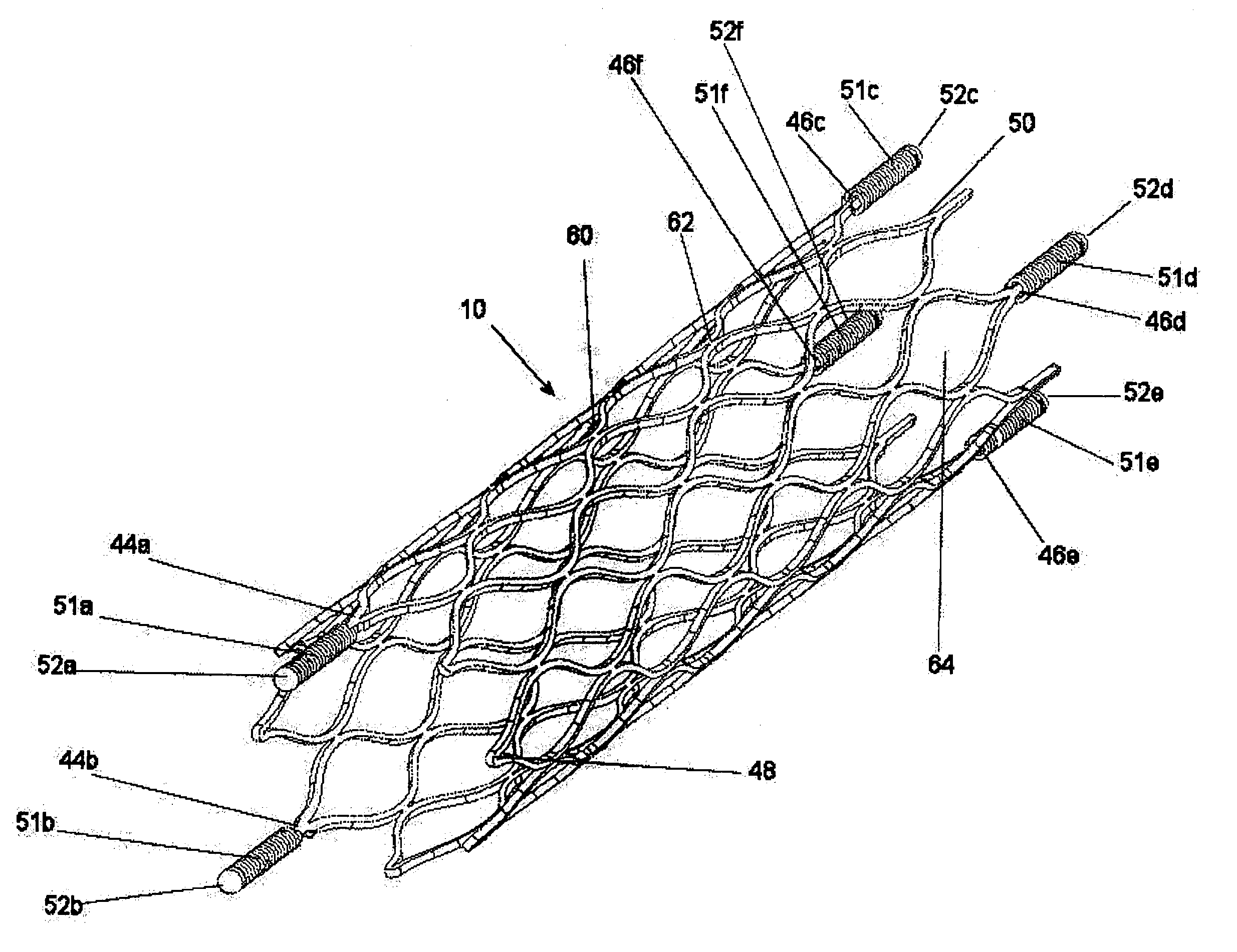
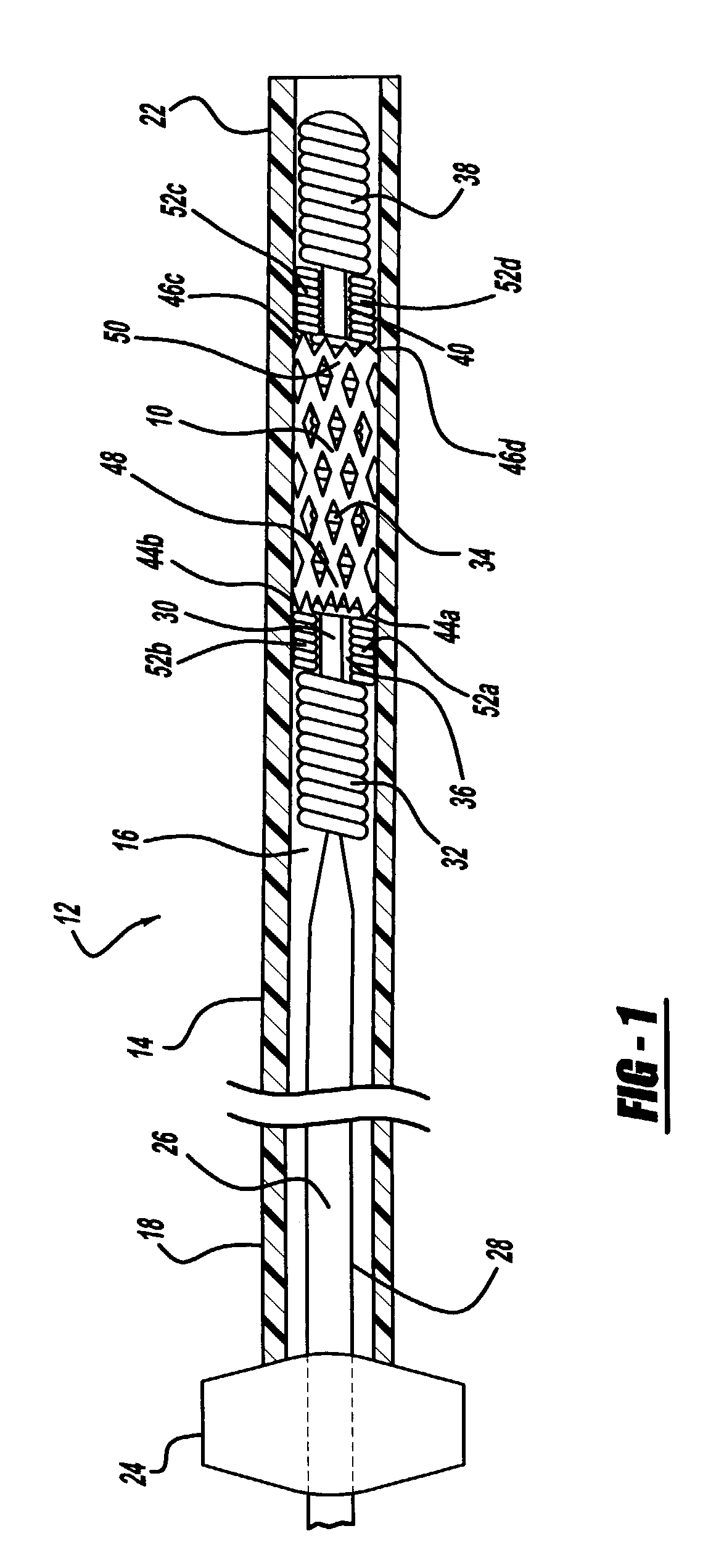
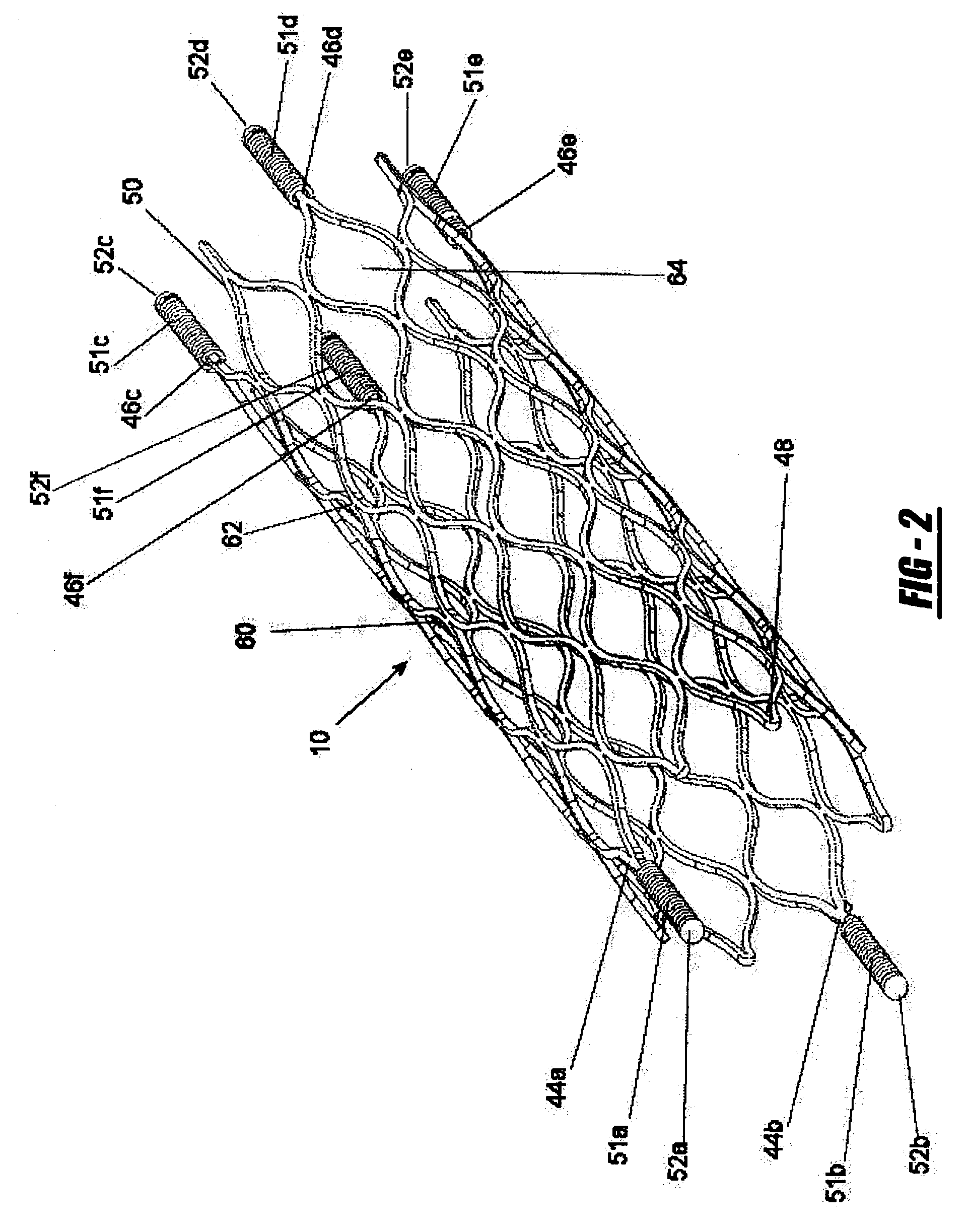
[0017]FIG. 1 illustrates an expandable intravascular stent 10, or aneurysm cover, and delivery system 12. The delivery system 12 includes a deployment catheter 14 which is an elongated tube having a lumen 16. The lumen 16 of the deployment catheter 14 has a diameter in the range of 0.010 inches to 0.25 inches, with a preferred diameter of approximately 0.021 inches. Preferably, the proximal section 18 of the deployment catheter 14 is formed of a nylon material having a durometer in the range of about 60D to 75D. The proximal section 18 of the deployment catheter 14 is sufficiently flexible to traverse a blood vessel, but is sufficiently rigid so that it may be passed through a blood vessel. The distal section 22 of the deployment catheter 14 is preferably formed of pellethane material having a durometer of between 25D and 55D, with a durometer of 40D being the preferred durometer.

[0018]The delivery system 12 includes a winged hub 24 coupled to the proximal section 18 of the deployme...


PUM


Abstract

Disclosed is a very small diameter intravascular stent, or aneurysm cover, which may be used to occlude, or partially occlude, an aneurysm in the human brain. The stent is comprised of a thin-walled skeletal tubular member formed of interconnected sinusoidal members to thereby form a pattern of cells along the skeletal tubular member. The stent also includes anchor members, which are comprised of a longitudinal leg member having a radiopaque coil disposed about the leg member, which serve to retain the stent during delivery of the stent.

Description

[0001]This patent application claims the benefit of provisional patent application Ser. No. 60 / 381,163 filed on May 16, 2002.BACKGROUND OF THE INVENTION[0002]1. Field of the Invention[0003]This invention relates to intravascular devices for implantation within a vessel of the body, and more particularly to a stent device which may be used in the treatment of blood vessel disorders. More specifically, the stent device may take the form of an aneurysm cover to be used in the treatment of aneurysms which occur within the brain.[0004]2. Description of the Prior Art[0005]On a worldwide basis, nearly one million balloon angioplasties are performed annually to treat vascular disease, including blood vessels clogged or narrowed by a lesion or stenosis. The objective of this procedure is to increase the inner diameter or cross-sectional area of the vessel passage, or lumen, through which blood flows. Another serious vascular defect is an area of weakened vessel wall that causes a bulge, or b...

Claims


Application Information

Patent Timeline
Patent Type & Authority Patents(United States)
IPC IPC(8): A61F2/06A61M29/00A61B17/12A61F2/00A61F2/82
CPCA61B17/12022A61B17/12118A61F2/91A61F2/915A61B2017/1205A61F2002/3008A61F2230/0013A61F2002/8486A61F2002/91541A61F2002/91558A61F2002/9534A61F2250/0098A61F2002/823
Inventor JONES, DONALD K.MITELBERG, VLADIMIR
Owner CODMAN & SHURTLEFF INC
Why Eureka
Try Eureka