System and method for ophthalmic lens manufacture

a technology of ophthalmic lenses and manufacturing methods, applied in the field of system and method for ophthalmic lens manufacture, can solve the problems of inability to justify the cost of acquiring and operating a surfacing laboratory, the inability of most of these entities to generate back surfaces of blanks, and the difficulty of hiring and training optical technicians to operate a surfacing laboratory, etc., to eliminate eliminate the effect of fabrication flaws, and minimize the transference of hea

Inactive Publication Date: 2001-12-13
NCRX OPTICAL SOLUTIONS
View PDF1 Cites 37 Cited by
  • Summary
  • Abstract
  • Description
  • Claims
  • Application Information

AI Technical Summary

Benefits of technology

[0021] It is a further object of the exemplary form of the present invention to provide a system and method for ophthalmic lens manufacture that significantly reduces the costs of acquiring and operating a full service surfacing and edging ophthalmic lens laboratory.
[0052] The system is farther operative to generate an appropriate lap tool for finishing the generated lens. The machining platform is operative to machine the surface of the lap tool responsive to the front surface data values, the prescription specifications, and, in cases where front surface radii are shorter than back surface radii, the data representing the size and shape of the frame. The orientation of the lap tool axes may be machined to match the orientation of the axes in the final lens so there is no need to rotate the lens blank in the surface blocking process in order to align the lens axes with the lap tool axes. There is also no need for prism blocking or prism ring tilting of the blocked lens blank for back surface generation.

Problems solved by technology

Semi-finished lens blanks have optically finished front surfaces; however, the back surfaces of these blanks need to be generated and fined and are then either polished or coated to produce finished uncut lenses.
The business volume of most of these entities cannot justify the costs of acquiring and operating a surfacing laboratory.
However, hiring and training optical technicians to operate a surfacing laboratory is not easy.
In many communities it is very difficult to find personnel that are trained in surfacing.
In addition to the significantly higher equipment and personnel costs of a surfacing lab, there are also higher ongoing costs for the additional lab space required.
Each of these machines or devices or augmentations is to varying degrees expensive to acquire and each of the machines or devices requires laboratory space.
Repeating the blocking process is necessary in part because the metallic block used for surfacing could interfere with the edging process.
If the standard surfacing block were also used during edging, this could result in the metal surfacing block coming into contact with the cutting or grinding surfaces of the edging machine thereby damaging the cutting or grinding surfaces of the edging machine and damaging or destroying the block in the process.
Additionally, the need to block a lens twice multiplies the opportunities for error and spoilage and requires the expenditure of time.
In both instances the lens is frequently tilted too much to apply an edge parallel to the normal at the geometric center of the front surface of the finished lens.
Applying an edge to a lens at any angle other than parallel to the front surface normal at the geometric center results in edges that are skewed and frequently thicker than necessary and with edge beads that have less than optimal orientations.
A blocking system optimized for edging, like "frame geometric center blocking", wherein the lens blank is blocked on the geometric center of the finished lens and where the normal at the geometric center of the front surface of the finished lens is parallel to the axis of rotation of the edging tool or edge grinding wheel, is not optimal for surfacing.
Production cycle times for generating lenses may be reduced by employing multiple surfacing and edging machines in the laboratory to generate pairs of lenses simultaneously, however duplication of equipment doubles the acquisition and operational costs of the laboratory.
Heat transfer into the lens blank from the heated blocking medium during the blocking procedure is a frequent cause of so called "lens warpage".
The greater the amount of heat transfer involved and the more uneven the distribution of that heat transfer is, the greater the chance of producing warpage and ruining the lens or producing a substandard lens.
This results in flaws or "waves" in the optics of the lens in the areas that underwent the flexure and is a common source of spoilage or of substandard lenses.
For this reason, a lens that has a polished edge with a polished bevel is more difficult to keep securely mounted and properly oriented in its frame.
Prior art systems for lens manufacture are inherently non-mobile, due to the large amounts of laboratory space required to store an inventory of lap tools and the many pieces of heavy laboratory equipment needed to generate and surface and finish lenses.
Thus, prior art systems cannot be easily transported to locations such as factories to manufacture safety lenses on-site or military theaters to support the optical needs of military personnel.

Method used


Image

  • System and method for ophthalmic lens manufacture
  • System and method for ophthalmic lens manufacture
  • System and method for ophthalmic lens manufacture

Examples


Embodiment Construction

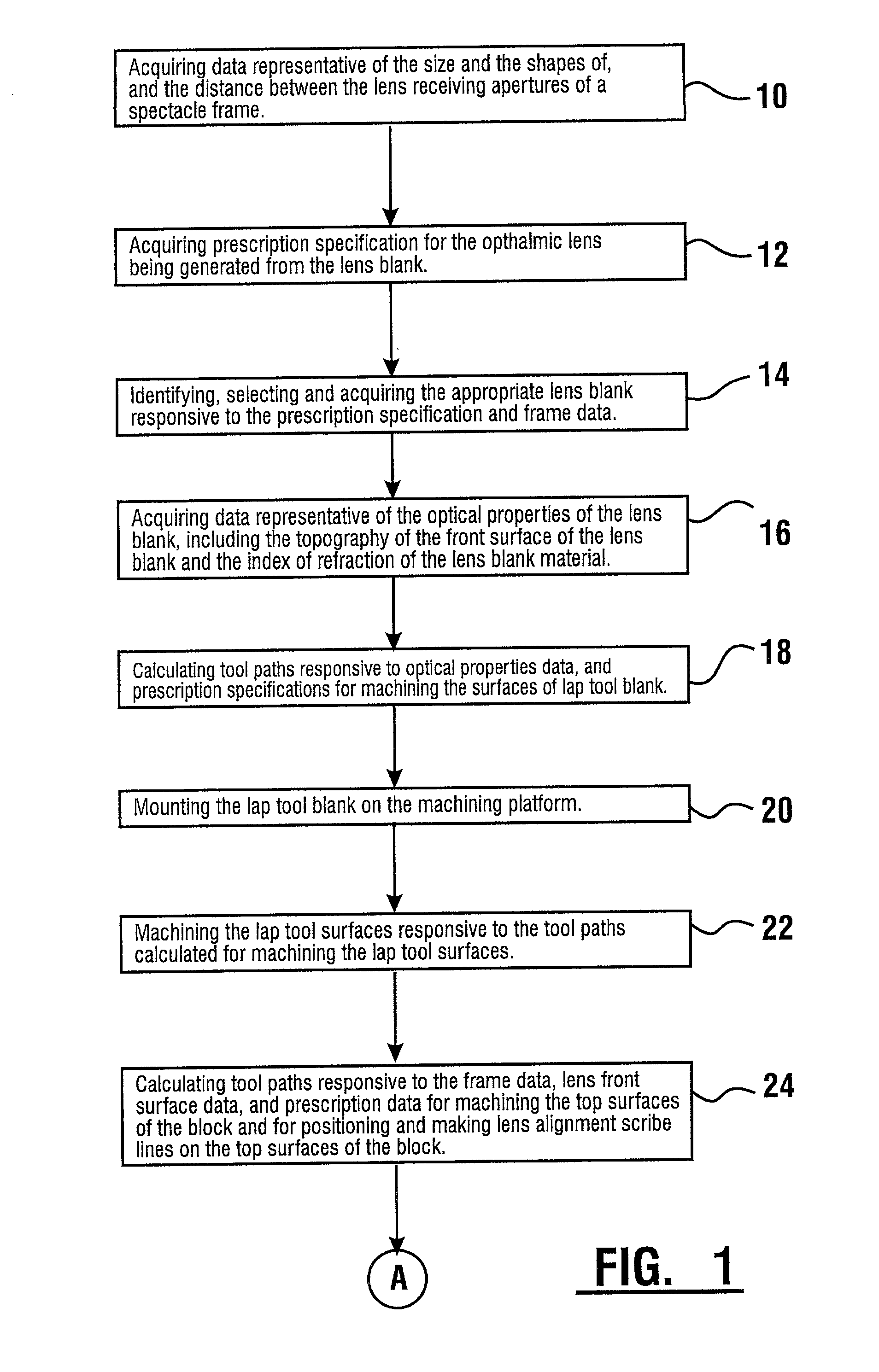
[0079] Referring now to the drawings and particularly to FIGS. 1, there is shown therein exemplary method steps of the present invention for generating an ophthalmic lens. Here the exemplary method comprises the step 10 of acquiring or collecting and temporarily or permanently storing data about the size and shape of the lens receiving aperture of a spectacle frame or other mounting structure, or alternately about the finished lens circumference and frame shape. In the exemplary embodiment frame data is collected in the form of a plurality of planar points (x,y) relative to a planar coordinate system.

[0080] The exemplary method further comprises the step 12 of acquiring or collecting and temporarily or permanently storing prescription specifications for the desired ophthalmic lens being generated from the lens blank. For the present exemplary invention, the prescription specifications includes information which describes the optical characteristics for the finished ophthalmic lens a...


PUM

PropertyMeasurementUnit
widthaaaaaaaaaa
surface topographyaaaaaaaaaa
physical propertiesaaaaaaaaaa

Abstract

A method and system for the manufacture of ophthalmic lenses comprising a computer (102) and a CNC machining platform (104) in operative connection with the computer. The CNC machining platform includes a mounting stage (110), a block (106) in releasable connection with the mounting stage, and a machining tool (112). When an unfinished lens blank (108) is properly mounted on the block, the computer is operative to direct the CNC machining platform to perform both back surface generation and patternless edging of the lens blank in one machining cycle. The computer is further operative to direct the CNC machining platform to machine a lap tool for each lens and machine a block for receiving each lens. The block is machined by the platform to include scribe lines for facilitating proper alignment of lens blank.

Description

[0001] This invention relates to the manufacture of ophthalmic lenses. Specifically this invention relates to a new system and method for surfacing, edging and finishing ophthalmic lenses.[0002] In the art of ophthalmic lens manufacture, a finished ophthalmic lens is usually made from finished uncut lenses or from semi-finished lens blanks. Finished uncut lenses are lenses that are optically finished on both front and back surfaces and only need to be edged to the proper shape and edge contour to become finished lenses. Most optical laboratories keep an inventory of single vision finished uncut lenses in various powers, sizes, and materials to take care of most of the more common single vision ophthalmic lens prescriptions.[0003] Semi-finished lens blanks have optically finished front surfaces; however, the back surfaces of these blanks need to be generated and fined and are then either polished or coated to produce finished uncut lenses. Finished uncut lenses are then edged to the ...

Claims


Application Information

Patent Timeline
Patent Type & Authority Applications(United States)
IPC IPC(8): B24B1/00B24B9/14B24B13/005B24B13/01B24B13/02B24B13/04B24B13/06B24B27/00B24B49/00B24B51/00
CPCB24B1/00B24B9/14B24B9/146B24B9/148B24B13/0031B24B13/005B24B13/0055B24B13/01B24B13/02B24B13/04B24B13/06B24B27/0076B24B51/00B29D11/00942
Inventor SIDERS, LARRY K.BAECHTEL, DONALD F.
Owner NCRX OPTICAL SOLUTIONS
Why Eureka
Try Eureka