

Pneumatic tire for front wheel of motorcycle
- Summary
- Abstract
- Description
- Claims
- Application Information
AI Technical Summary
Benefits of technology
Problems solved by technology
Method used
Image

Examples
first embodiment
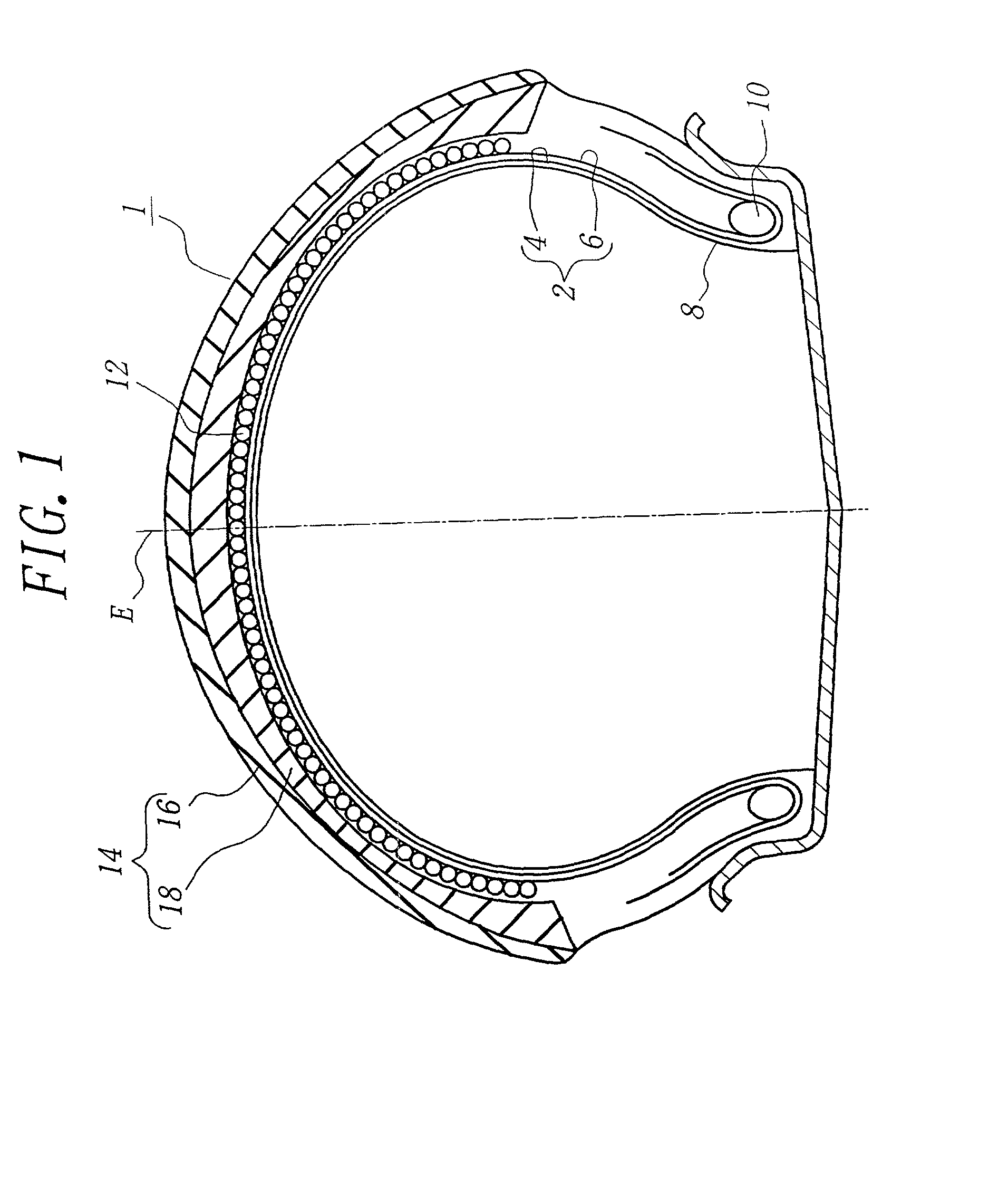
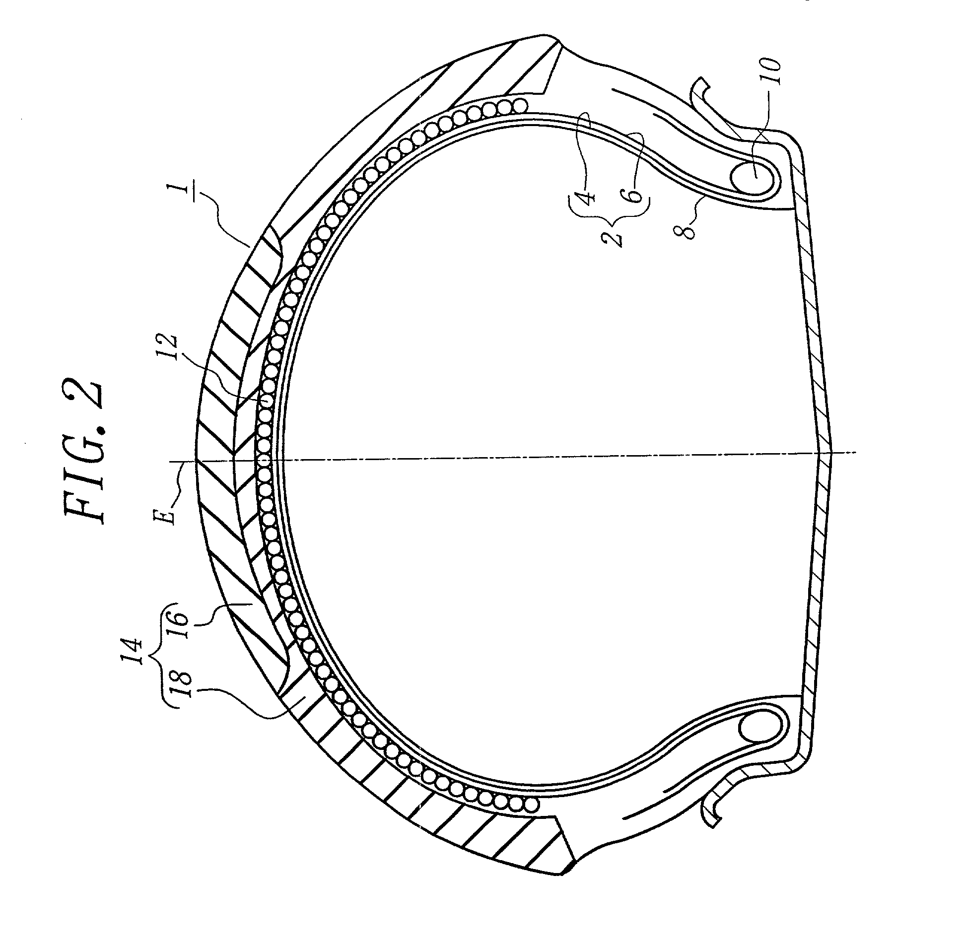
[0042] In FIG. 1 is shown the tire according to the invention, wherein numeral 1 is a pneumatic tire for the front wheel of the motorcycle (not shown), and numeral 2 a carcass comprised of two carcass plies 4, 6. In each of the carcass plies 4, 6 are embedded a plurality of organic fiber cords such as nylon cords so as to extend at a cord angle of 60-90.degree. with respect to an equatorial plane E of the tire.
[0043] The tire 1 comprises a belt 12 disposed on an outer periphery of the carcass 2 in a radial direction of the tire. The belt 12 is a spiral belt layer formed by spirally winding a continuous rubberized cord or a continuous ribbon-shaped body containing plural cords therein in a widthwise direction of the tire so as to extend the cord substantially in a circumferential direction of the tire. As the cord is preferably used a high strength and high tenacity aramid fiber cord (Kevlar, trade name) or the like.
[0044] A tread 14 is disposed on an outer periphery of the belt 12 i...
third embodiment
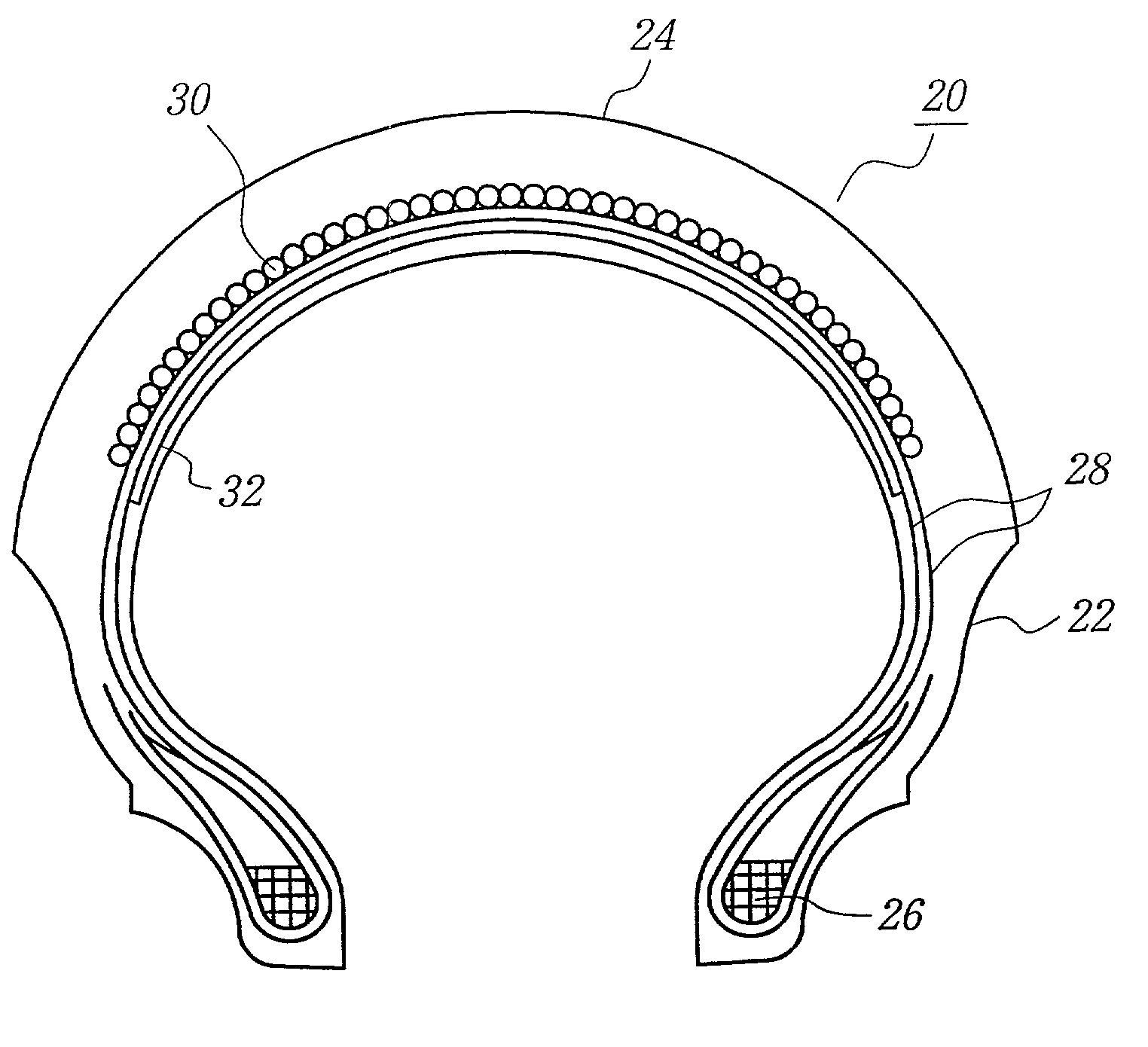
[0049] In FIG. 3 is shown the pneumatic tire for the front wheel of the motorcycle according to the invention, wherein numeral 20 is a pneumatic tire, numeral 22 a sidewall portion, numeral 24 a tread portion extending between a pair of the sidewall portions 22, numeral 26 a bead core, and numeral 28 a carcass toroidally extending between a pair of the bead cores 26. The carcass 28 is comprised of two rubberized plies each containing organic fiber cords arranged at a cord angle of 60-90.degree. with respect to the equatorial plane of the tire.
[0050] Further, numeral 30 is a belt disposed on an outer periphery of the carcass 28 in the radial direction, which is a spiral belt layer formed by spirally winding a continuous rubberized cord or a continuous ribbon-shaped body containing plural cords therein in a widthwise direction of the tire so as to extend the cord substantially in a circumferential direction of the tire, and numeral 32 a reinforcing layer arranged inside the carcass 28...
fourth embodiment
[0052] In FIG. 4 is the pneumatic tire for the front wheel of the motorcycle according to the invention, wherein the reinforcing layer 32 is arranged on a surface of an innerliner 34 (or inner surface of the tire in the radial direction). Even in this tire, not only the bending rigidity of the tread but also the shearing rigidity between the tread surface and the carcass are held at a high level.
PUM
 Abstract
Description
Claims
Application Information