Vehicle light with high resistance to heat

a technology of high resistance and heat resistance, which is applied in the direction of vehicle headlamps, transportation and packaging, light and heating equipment, etc., can solve the problems of deformation and softening of some of the components of headlights, and achieve the effect of increasing heat resistan

Inactive Publication Date: 2002-01-03
VALEO VISION SA
View PDF0 Cites 13 Cited by
  • Summary
  • Abstract
  • Description
  • Claims
  • Application Information

AI Technical Summary

Benefits of technology

0003] One object of the present invention is to provide a headlight (i.e. an illuminating or signalling device, as defined...

Problems solved by technology

Such a temperature can cause deformation and softening of some of the...

Method used


Image

  • Vehicle light with high resistance to heat
  • Vehicle light with high resistance to heat
  • Vehicle light with high resistance to heat

Examples


Embodiment Construction

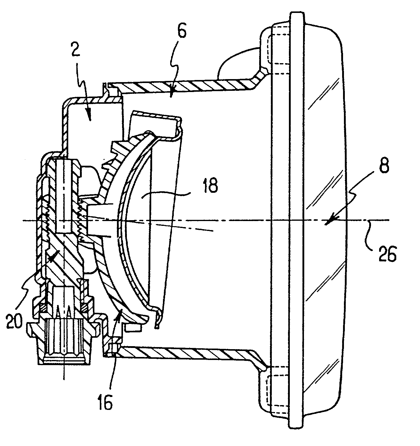
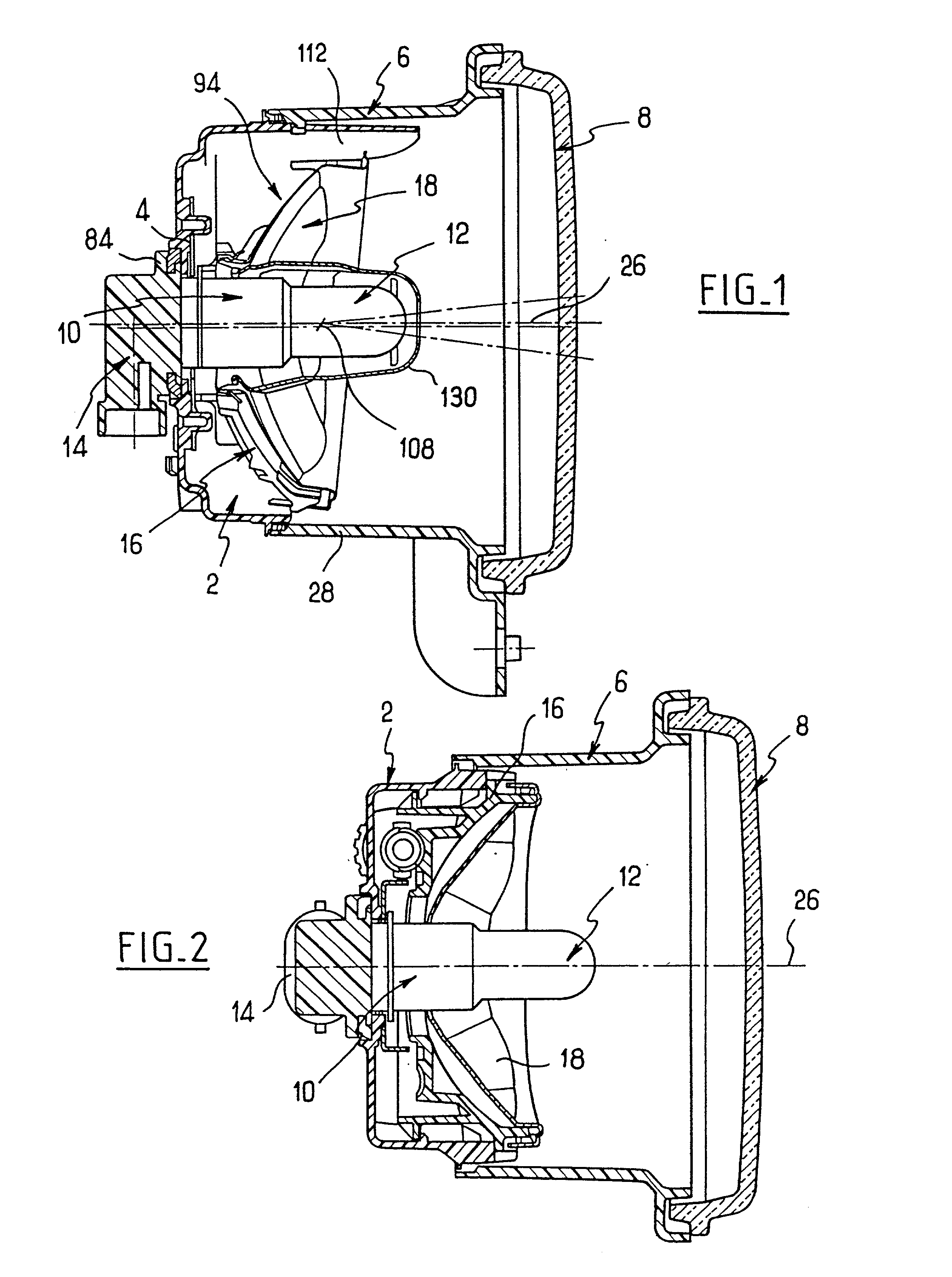
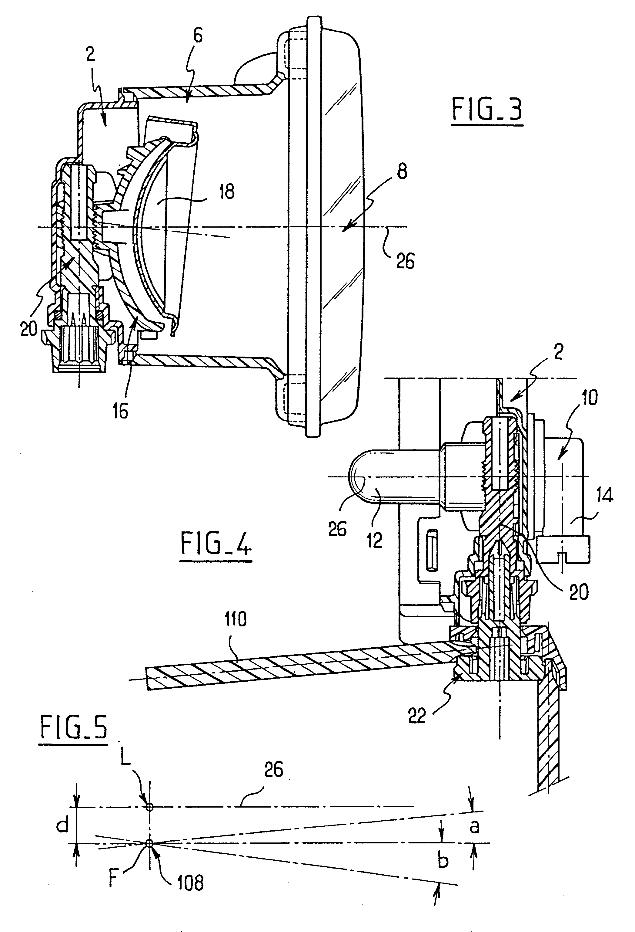
[0042] Reference is first made to FIGS. 1 to 3. In this description, the headlight is in fact a fog penetrating light, or foglight, unit. It comprises a casing at the rear of the unit, a press-formed metal plate 4 fixed to the casing, an intermediate piece 6 fixed to the casing, and a front glass 8 fixed to the intermediate piece 6. The headlight also includes a lamp holder 10 fixed to the casing and to the plate 4, a lamp 12 and a connector 14, the lamp and connector being fixed to the lamp holder. The unit also includes a cradle 16 which is fixed to the casing, and a reflector 18 fixed to the cradle. It further includes an adjusting screw 20 and an adjusting knob 22 which is fixed to the screw 20, as can be seen in particular in FIG. 4. These various parts of the light will now be described in greater detail.

[0043] Accordingly, reference is now made to FIGS. 7 to 9. The casing 2 essentially consists of a base wall 24 which is generally flat and at right angles to a horizontal axis...


PUM


Abstract

A vehicle foglight, or other light for illuminating or signalling purposes, has a casing and a reflector, with a cradle which connects the reflector to the casing and which has an aperture in its upper part such that the cradle is U-shaped. The lamp is mounted in the aperture and the rear wall of the casing carries a metal plate. Heat from the lamp is dissipated so that plastics components are not unduly heated.

Description

[0001] This invention relates to lights, especially for a motor vehicle, in particular where the purpose of the light is to provide illumination, but also including lights having as their only or primary purpose the giving of an indication or signal. These various kinds of lights will be referred to generically in this Application, for convenience, as headlights.[0002] European published patent specification No. 0 847 894 discloses an illuminating or signalling device for a vehicle which comprises a casing, a fixed lamp and a reflector mounted for movement in the casing and being directly connected to the casing. In some applications, particularly in a foglight, the temperature in the upper part of the reflector can reach more than 200.degree. C. Such a temperature can cause deformation and softening of some of the components of the headlight, particularly if they are of plastics material. The connection between the reflector and casing is particularly critical in this regard, and t...

Claims


Application Information

Patent Timeline
IPC IPC(8): B60Q1/04B60Q1/068B60Q1/26F21V14/04F21V29/15
CPCB60Q1/0683B60Q1/26F21S48/1757F21S48/32F21S41/675F21S45/10
Inventor DINANT, FRANK
Owner VALEO VISION SA
Why Eureka
Try Eureka