
Drive control apparatus for stepping motor

Inactive Publication Date: 2002-01-24
CANON KK
View PDF0 Cites 10 Cited by
  • Summary
  • Abstract
  • Description
  • Claims
  • Application Information

AI Technical Summary

Problems solved by technology

However, in the case where such a micro step driving mode is used to drive the shutter blade, lens or other delicate instruments by the stepping motor and stop to hold the rotor of the stepping motor in the position corresponding to the energized electrical current to the coil, there is a problem that stopping positions vary due to backlash of a reduction gear of a gear or a screw or due to inertial friction of a sliding portion.
Therefore, vibration or step out occurs to make it impossible to smoothly drive the driven object at high speed and to position the same at high speed and accuracy.
In the case where the micro step driving mode is used to drive the lens or others by the stepping motor and stop to hold the rotor of the stepping motor in the position corresponding to the energized electrical current to the coil, there is the problem that the stopping positions vary due to the backlash of the reduction gear of the gear or screw or due to the inertial friction of the sliding portion.
As another problem of the micro step control, if a driving force is low for positioning the rotor in a position where the rotor is stopped, the rotor is influenced by the friction or driving load and cannot stop at the predetermined position, leaving a difference in stopping position.
Especially, when the position of the rotor comes closer to an original position to be positioned by the micro step control, the rotational driving force becomes lower which is produced to try to position in the original position so that only a slight friction force is produced which makes it difficult to position in the original position.
Increasing the driving force can reduce the difference in stopping position, which requires high current flown in the coil, so that there is a disadvantage of consuming high power and of heating the motor, which results in a poor characteristic.
The above conventional stepping motor of small size shown in FIG. 44 has a disadvantage of having an outer shape of the motor in larger size since the casing 103, bobbin 101, stator coil 105 and stator yoke 106 are concentrically arranged on an outer periphery of the rotor.
There is also a disadvantage of not increasing output of the motor since magnetic flux generated by energizing the stator coil 105 mainly passes an end surface 106a1 of the stator teeth 106a and an end surface 106b1 of the stator teeth 106b as shown in FIG. 45 and is not effectively applied on the rotor magnet 111.

Method used


Image

  • Drive control apparatus for stepping motor
  • Drive control apparatus for stepping motor
  • Drive control apparatus for stepping motor

Examples


embodiment 2

[0146] Because the configuration of the embodiment is the same as the first embodiment, the description thereof is omitted and the control flow different from there will be described. The micro step drive is as described in the first embodiment. Next, the switching of the full step drive and the micro step drive will be described.

[0147] It is only natural that the rotational speed and the output torque of the motor is higher in the case of the full step drive than in the case of the micro step drive and that the rotational resolution of the output axis of the motor is higher in the case of the micro step drive than in the case of the full step drive. For this reason, when a driven object is to be positioned at some predetermined position, if it is far from a target position, it is driven at a high speed by the full step drive and, when coming adjacent to the target position on the way, driven by the micro step drive so as to perform an accurate positioning in such a manner that a hi...

embodiment 3

[0183] The description of a motor configuration and a practical step drive of the present embodiment will be omitted as it is as described in the first embodiment.

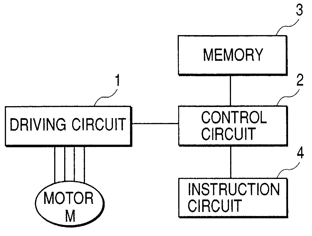
[0184] FIG. 16 is a block diagram of the third embodiment. In FIG. 16, reference symbol M denotes a motor, reference numeral 1 a driving circuit, reference numeral 2 a control circuit, reference numeral 3 a memory (storing means), reference numeral 4 an instruction circuit and reference numeral 5 calculation means. The driving circuit 1 is for letting the energized electrical current designated from the control circuit 2 flow to the coil of the motor M and is composed, for example, of the circuit having H circuits in the corresponding number of coils which can selectively energize the coils composed of four transistors in both directions in the forward and the reverse directions. In the present embodiment, because the description is made by using a stepping motor of two phases, it is provided with two pieces of the H circu...

embodiment 4

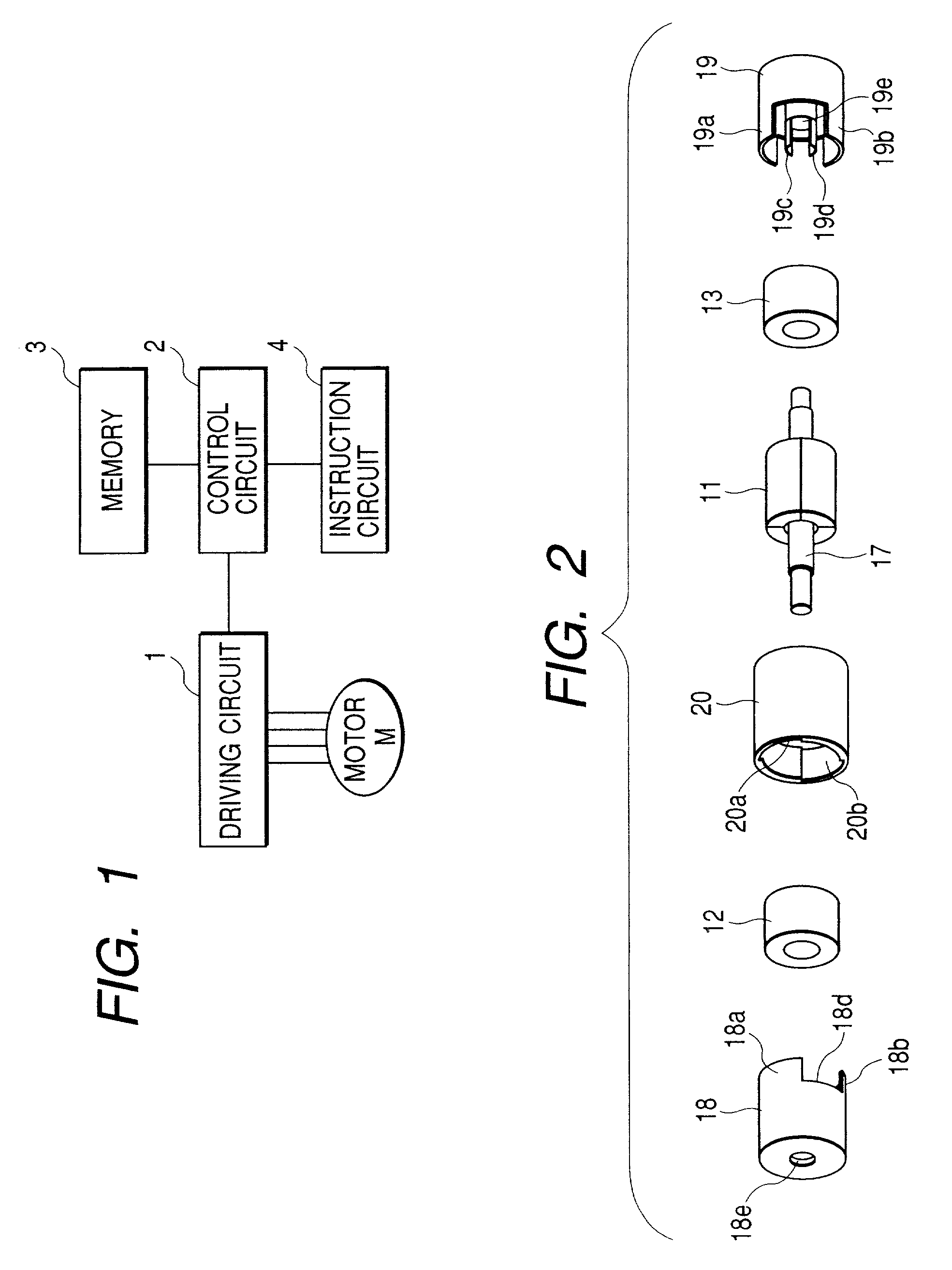
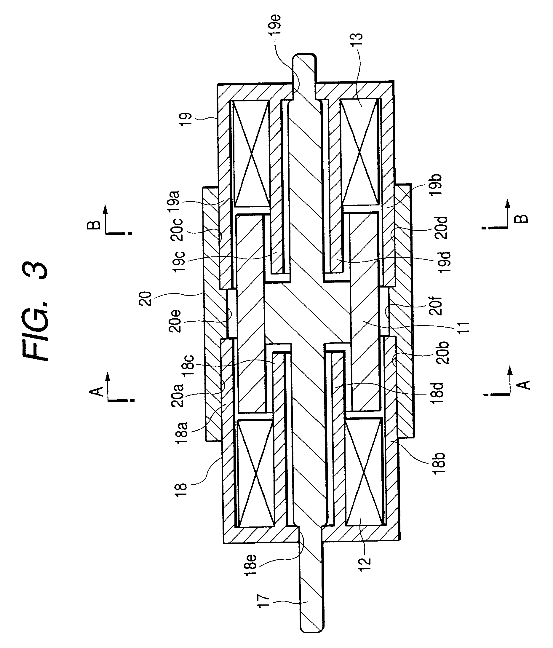
[0233] FIGS. 22 through 29 show a fourth embodiment of the present invention. FIG. 22 is an exploded perspective view of an iris blade drive mechanism; FIG. 23, an exploded perspective view of a first drive; FIG. 24, an exploded perspective view of a second drive; FIG. 25, a cross-sectional view of the first drive; and FIGS. 26 through 29, cross-sectional views showing the relationship between the first and second drives and a motor consisting of output means. Because the second drive has the same structure as the first drive, the cross-sectional view of the second drive is similar to that of the first drive in FIG. 25.

[0234] In FIGS. 22 through 29, a reference numeral 1 indicates a cylindrical magnet, a component of a rotor. The side of the magnet 1 is divided in the circumferential direction into n (10 for the embodiment) magnetized sections 1a, 1b, 1c, 1d, 1e, 1f, 1g, 1h, 1i, and 1j which are magnetized so that they are alternately S and N poles. That is, the magnetized sections ...


PUM


Abstract

A driving apparatus for a stepping motor, especially which, in micro step driving, partly changes a combination of an energization value to each phase of a motor depending upon a rotational direction of the motor and accurately controls a stopping position of a driven object which is driven by the motor.

Description

[0001] 1. Field of the Invention[0002] The present invention relates to a method and apparatus for driving a stepping motor, and more particularly, to a method and apparatus for driving a stepping motor using a micro step driving mode where an exciting current which is increased and decreased step by step is energized to each phase.[0003] 2. Related Background Art[0004] Various instruments are driven using a motor driven by pulse signals, for example, a stepping motor. A shutter device, for example, where a shutter blade is driven to be opened and shut using the stepping motor is known as disclosed in Japanese Utility Model Application Laid-Open No. 60-140934, Japanese Patent Publication No. 6-64281 and the like. A lens barrel device where a lens is moved along an optical axis using the stepping motor is also known as proposed in Japanese Patent Application Laid-Open No. 6-250070, for example. In the above mentioned stutter device and lens barrel, driving frequency or number of driv...

Claims


Application Information

Patent Timeline
IPC IPC(8): H02K7/116H02K37/12H02P8/22H02P8/30
CPCH02K7/116H02K37/12H02P8/22H02P8/30
Inventor AOSHIMA, CHIKARA
Owner CANON KK
Features
  • Generate Ideas
  • Intellectual Property
  • Life Sciences
  • Materials
  • Tech Scout
  • Unparalleled Data Quality
  • Higher Quality Content
  • 60% Fewer Hallucinations
Learn More