Dental prosthesis manufacturing process, dental prosthesis pattern @$amp; dental prosthesis made thereby

Inactive Publication Date: 2002-01-31
NAT DENTEX LLC
View PDF1 Cites 70 Cited by
  • Summary
  • Abstract
  • Description
  • Claims
  • Application Information

AI Technical Summary

Problems solved by technology

Although this computer aided design equipment proposes to eliminate conventional investment casting, it suffers from a number of drawbacks that prevent greater utilization of this technology.
First, it is impractical to make dental prosthesis from such precious metals as gold and pla

Method used


Image

  • Dental prosthesis manufacturing process, dental prosthesis pattern @$amp; dental prosthesis made thereby
  • Dental prosthesis manufacturing process, dental prosthesis pattern @$amp; dental prosthesis made thereby
  • Dental prosthesis manufacturing process, dental prosthesis pattern @$amp; dental prosthesis made thereby

Examples


Embodiment Construction

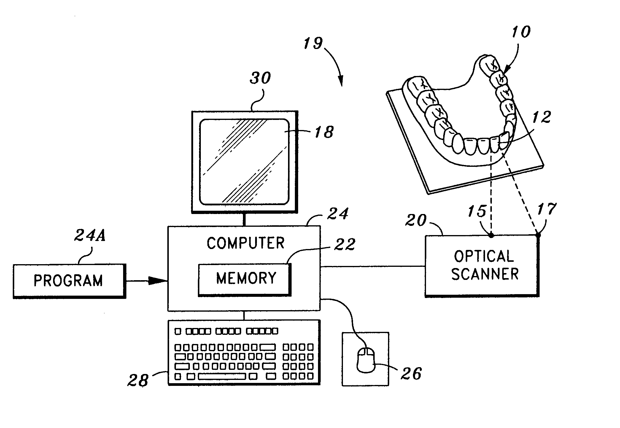
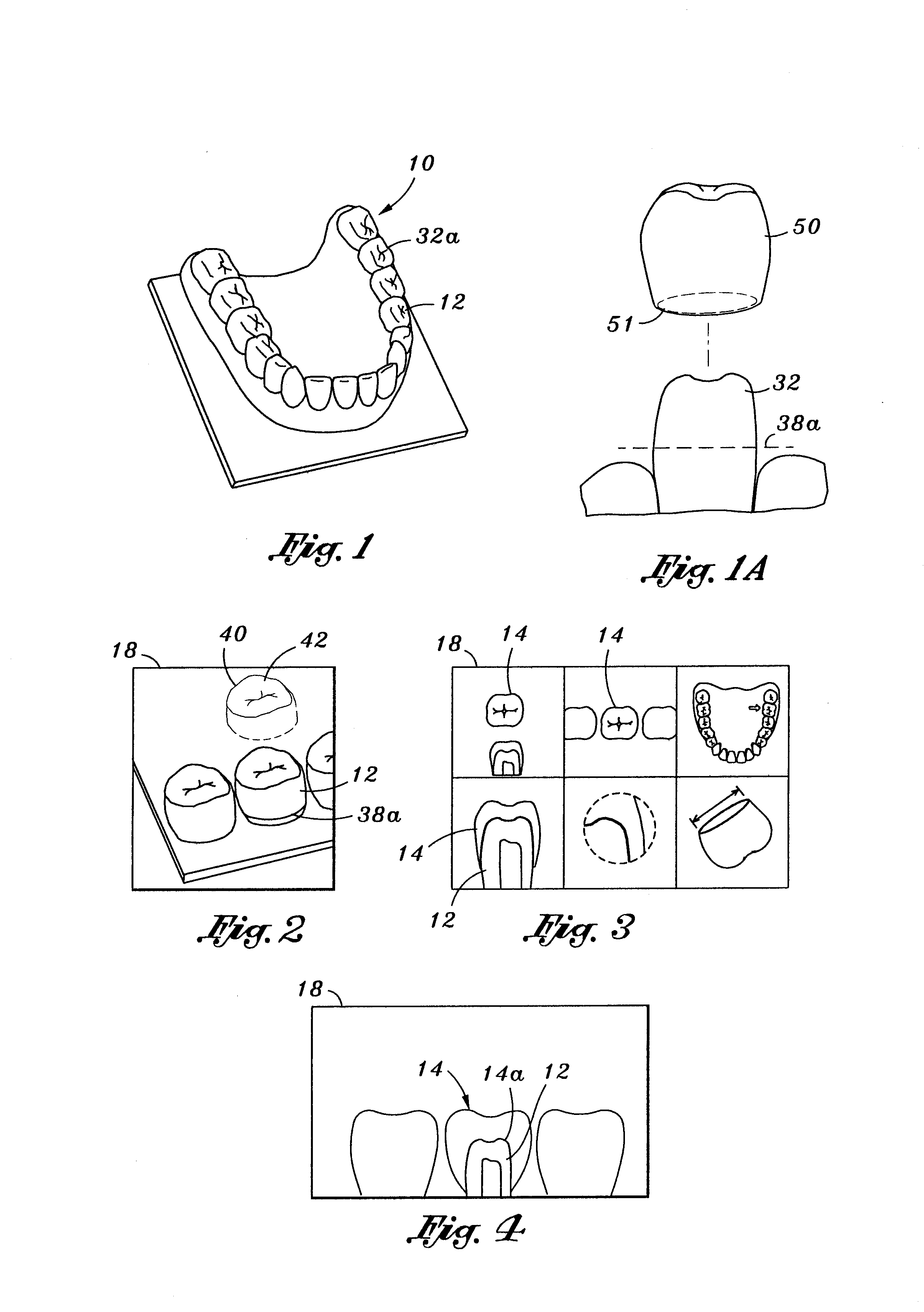
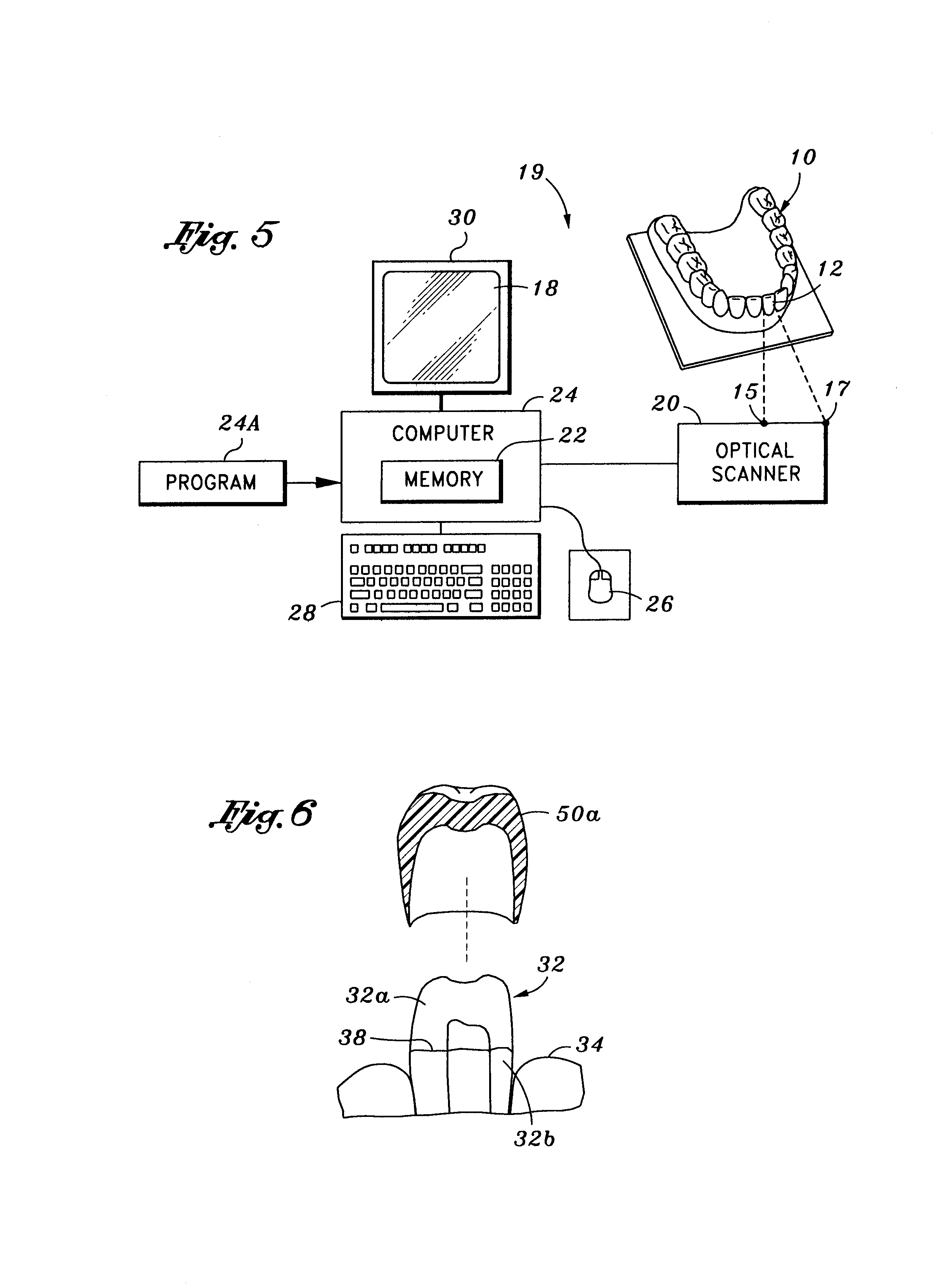
[0021] In accordance with conventional techniques, a model of a patient's dentition is made. The upper jaw portion 10 of such a model is shown in Fig. 1. A lower jaw portion of this model is also used to collect tooth surface data, but is not shown. For purposes of illustration as shown in Fig. 6, an actual stump 32 to which a crown type 50a dental prosthesis is to be attached includes a drilled away portion 32a and an undisturbed portion 32b next to the patient's gum 34. Where the contiguous borders of the portions 32a and 32b meet, as defined by the line 38, a margin is formed. The jaw portion 10 includes a replicate 32a of the stump 32 to which the crown type dental prosthesis 50a is to be attached.

[0022] As shown in Fig. 6, computer aided design equipment 19 creates an image of a dental prosthesis based on data collected from the model of the patient's dentition. As illustrated in Fig. 7, computer aided design equipment sold under the trademark LabQraft by Dentalmatic Technologi...


PUM


Abstract

<heading lvl="0">Abstract of Disclosure</heading> A dental prosthesis is made by first forming a model of a patient's dentition. A three dimensional digital data corresponding to the surfaces of the model is then created. Based on this data, a three dimensional digital data file is then created substantially corresponding to the dental prosthesis to be manufactured. The three dimensional digital data of the dental prosthesis to be manufactured is next transmitted to automated prototyping equipment, and using the automated prototyping equipment, a wax pattern of the dental prosthesis is manufactured based upon this three dimensional digital data of the dental prosthesis. Finally, using this wax pattern in the lost wax investment casting process, the dental prosthesis is made. Prior to investment casting, marginal edges of the wax pattern are adjusted manually.

Description

Background of Invention[0001] Computer technology has advanced to the point where a dental prosthesis may be milled from a solid block of material based on three-dimensional digital data corresponding to a proposed shape of the dental prosthesis. The dentist first makes an impression of a patient's existing dentition. Typically, this includes nearby surfaces where the prosthesis is to be located in the patient's mouth. This is accomplished by the dentist first drilling away any unwanted dental tooth structure and then having the patient bite into an impression material that forms a negative impression of the patient's dentition, including the tooth structure to which the dental prosthesis is to be attached. This negative impression is then filled with dental die stone to make a model of the tooth structure to which the dental prosthesis is to be attached and adjacent teeth, particularly the teeth immediately above and to the sides of the tooth structure to which the dental prosthesi...

Claims


Application Information

Patent Timeline
IPC IPC(8): A61C13/00
CPCA61C13/0004
Inventor O@$APOS, BRIEN, J., G.
Owner NAT DENTEX LLC
Why Eureka
Try Eureka