Eureka AIR delivers breakthrough ideas for toughest innovation challenges, trusted by R&D personnel around the world.

Catalytic combustor

Inactive Publication Date: 2002-02-21
TOYOTA CENT RES & DEV LAB INC
View PDF0 Cites 6 Cited by
  • Summary
  • Abstract
  • Description
  • Claims
  • Application Information

AI Technical Summary

Benefits of technology

[0011] With the catalytic combustor in accordance with the present invention, pressure loss is small even with a reduced size and weight. And by supporting the oxidation catalyst on at least one part of the surface of the heat-conductive separator, heat can be conducted to the members to be heated prior to other members. In addition, the projections and depressions provided in the surface of the heat-conductive separator, which faces the combustion chamber, enable a flow of a mixture of combustible materials and combustion-assisting materials to partly stay therearound, whereby stable combustion can be effected even at widely ranged flow rates. Furthermore, if combustion-blocking materials such as water enter the combustion chamber in such a case that the catalytic combustor in accordance with the present invention is used in the fuel reformer, the projections and depressions provided in the heat-conductive separator enable the diffusion range of the combustion-blocking materials to be reduced. Accordingly, the risk of flame failure decreases, and, even if flame failure occurs, the diffusion range thereof becomes narrow.
[0031] In addition, the catalytic combustors in accordance with the present invention can achieve the operational effect that the catalytic combustor can be made small and light as required under conditions capable of restraining the degradation of the various performance of the catalytic combustors to a minimum.

Problems solved by technology

These combustors as the conventional heating devices, however, have disadvantages as follows.
With this arrangement, however, the miniaturized combustion catalysts cause the increment of pressure loss with the result that fuel and air are required to be supplied under high pressure.
Hei 6-111838 does not have a serious problem concerning pressure loss, but, where the supply rate of fuel or the like is varied for temperature adjustment, or where incombustible materials such as water is mixed with fuel in the case of exhaust gases of fuel cells being used as fuel, etc., it is impossible to keep the stable combustion, and consequently, flame failure may occur.
In this case, uniform heating cannot be performed.
In addition, the combustion chambers having slits-like configurations make it difficult to supply fuel to every combustion chamber uniformly, and accordingly, uniform heating of the members to be heated becomes impossible.
Accordingly, the risk of flame failure decreases, and, even if flame failure occurs, the diffusion range thereof becomes narrow.
However, if the length in the directions perpendicular to the fluid flow is too short, the effect of generating disordered flows decreases.
The reduced opening diameter thereof enables the increment of the supply flow rate, and accordingly the possibility of backfire decreases even when heating is carried out with a low output.

Method used


Image

  • Catalytic combustor
  • Catalytic combustor
  • Catalytic combustor

Examples


embodiment

[0037] [Embodiment]

[0038] Hereinafter, the catalytic combustor in accordance with the present invention will be explained in more detail based on several embodiments.

[0039] [Catalytic Combustor]

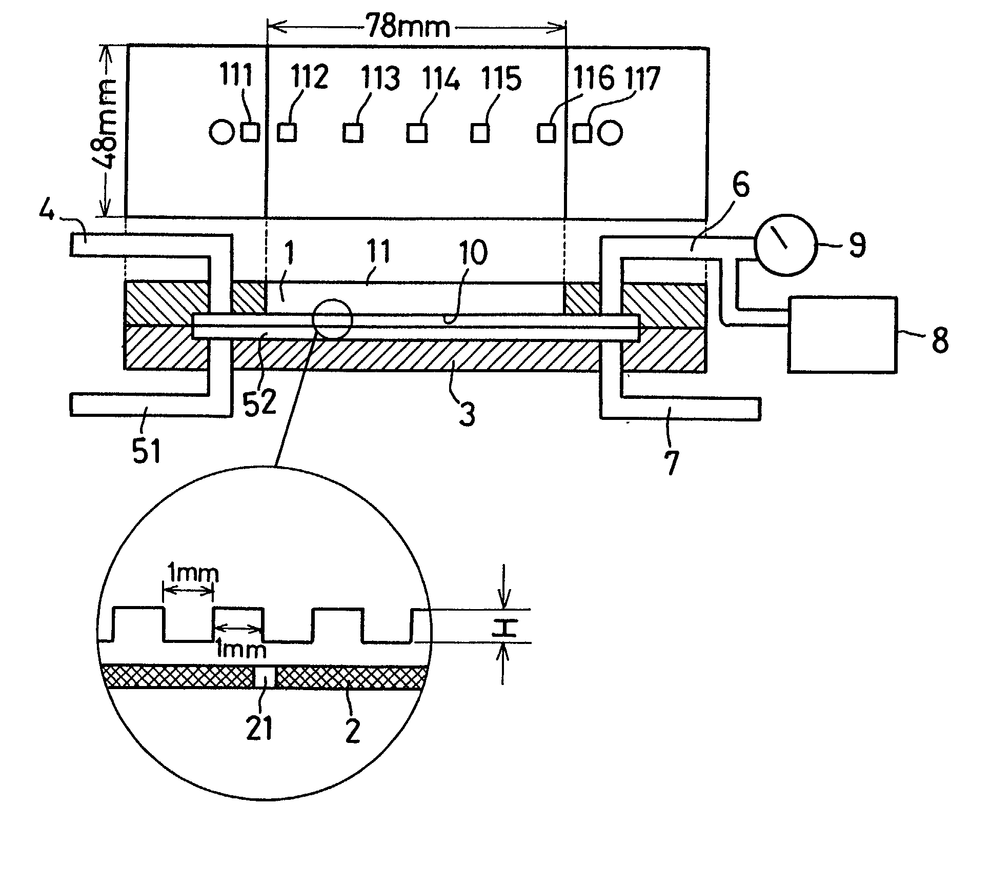
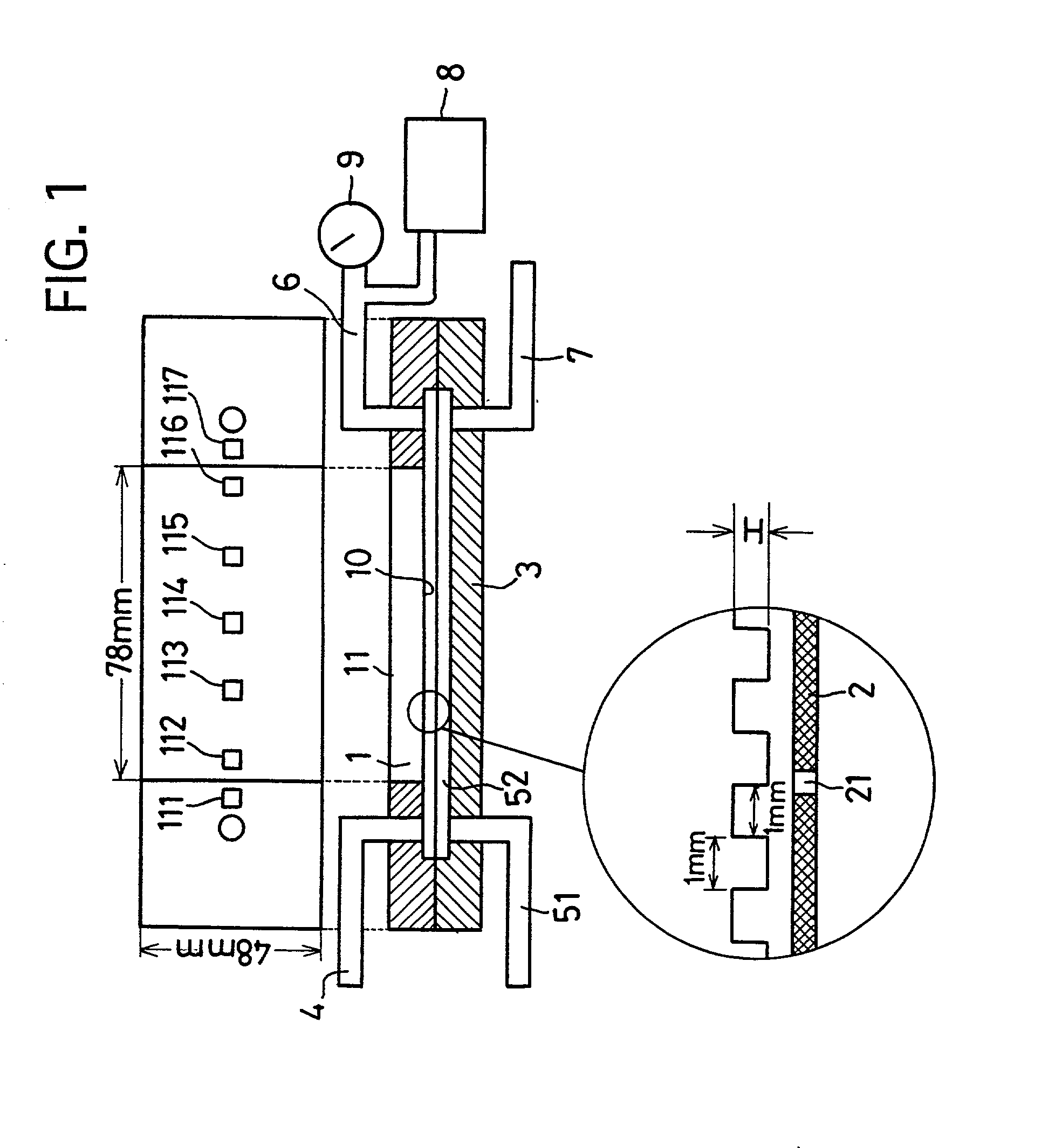
[0040] The catalytic combustor which was used in tests is schematically illustrated in FIG. 1. The catalytic combustor of the present embodiment includes a heat-conductive separator 1 which has projections and depressions in one part 10 (78 mm.times.49 mm) of a surface which faces a combustion chamber, a catalyst layer (not shown) which is supported on the part 10, a wall 2 which has supply ports 21 (opening diameter 0.3 mm, 12 ports) for supplying fuel toward the part 10, faces the heat-conductive separator 1, and defines the combustion chamber with the heat-conductive separator 1, a plate-like member 3 which is located to face the wall 2 on the opposite side of the combustion chamber and defines one part (52) of a fuel supply passage, an air supply passage 4 which is communicated with a sup...


PUM

PropertyMeasurementUnit
Fractionaaaaaaaaaa
Heightaaaaaaaaaa
Lengthaaaaaaaaaa

Abstract

The present invention provides a small-sized and lightweight catalytic combustor which can operate stably against variations of members to be heated. The catalytic combustor includes a heat-conductive separator for defining a combustion chamber and conducting heat to a member to be heated, the separator has projections and depressions in at least one part of a surface facing the combustion chamber, and an oxidation catalyst is supported on at least one part of the projections and depressions of the heat-conductive separator. By providing the projections and depressions in the surface of the heat-conductive separator, which faces the combustion chamber, a flow of a mixture of combustible materials and combustion-assisting materials can partly stay around the projections and depressions to enable a stable combustion thereof even at various flow rates.

Description

[0001] 1. Field of the Invention[0002] The present invention relates to a catalytic combustor for heating members to be heated.[0003] 2. Description of Related Art[0004] Fuel reformers for use in fuel cells generate hydrogen by bringing organic compounds into contact with fuel reforming catalysts in high temperature atmospheres. To keep high temperature atmospheres, some heating devices are required. The heating devices are auxiliary facilities of the fuel reformers, and accordingly it is preferable to make the heating devices as small and light as possible. Where the fuel cells are used in motor vehicles or the like, it is much required to make the heating devices small and light. The output of the fuel cells greatly varies with the operating conditions of motor vehicles, and accordingly, it is preferable that the fuel reforming rate of the fuel reformers, as well as the energy generated by the heating devices can greatly vary with the output of the fuel cells. More specifically, t...

Claims


Application Information

Patent Timeline
IPC IPC(8): F23D11/40B01J23/42F23C13/00H01M8/06
CPCF23C13/00
Inventor NAGANO, SUSUMUOHSAWA, KATSUYUKI
Owner TOYOTA CENT RES & DEV LAB INC
Why Eureka
Eureka Blog
Learn More