Method for manufacturing a golf club

a manufacturing method and golf club technology, applied in golf clubs, sport equipment, golf, etc., to achieve the effects of short time, high strength, and facilitation of alpha phase precipitation

a manufacturing method and golf club technology, applied in golf clubs, sport equipment, golf, etc., to achieve the effects of short time, high strength, and facilitation of alpha phase precipitation

US20020022534A1Inactive Publication Date: 2002-02-21ENDO MFG COMPANY

Image

  • Method for manufacturing a golf club
  • Method for manufacturing a golf club
  • Method for manufacturing a golf club

Examples


Embodiment Construction

[0026] Hereinafter is explained an embodiment of a golf club of the invention with reference to the attached drawings.

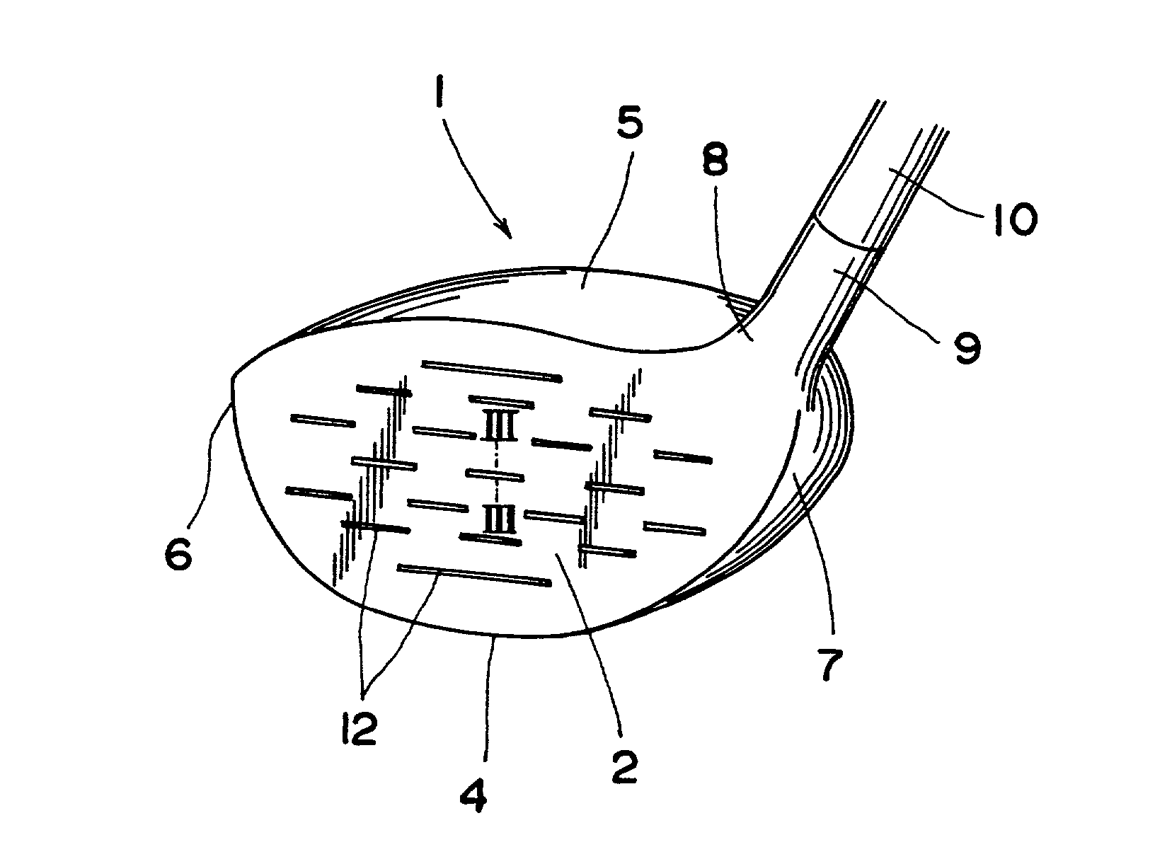
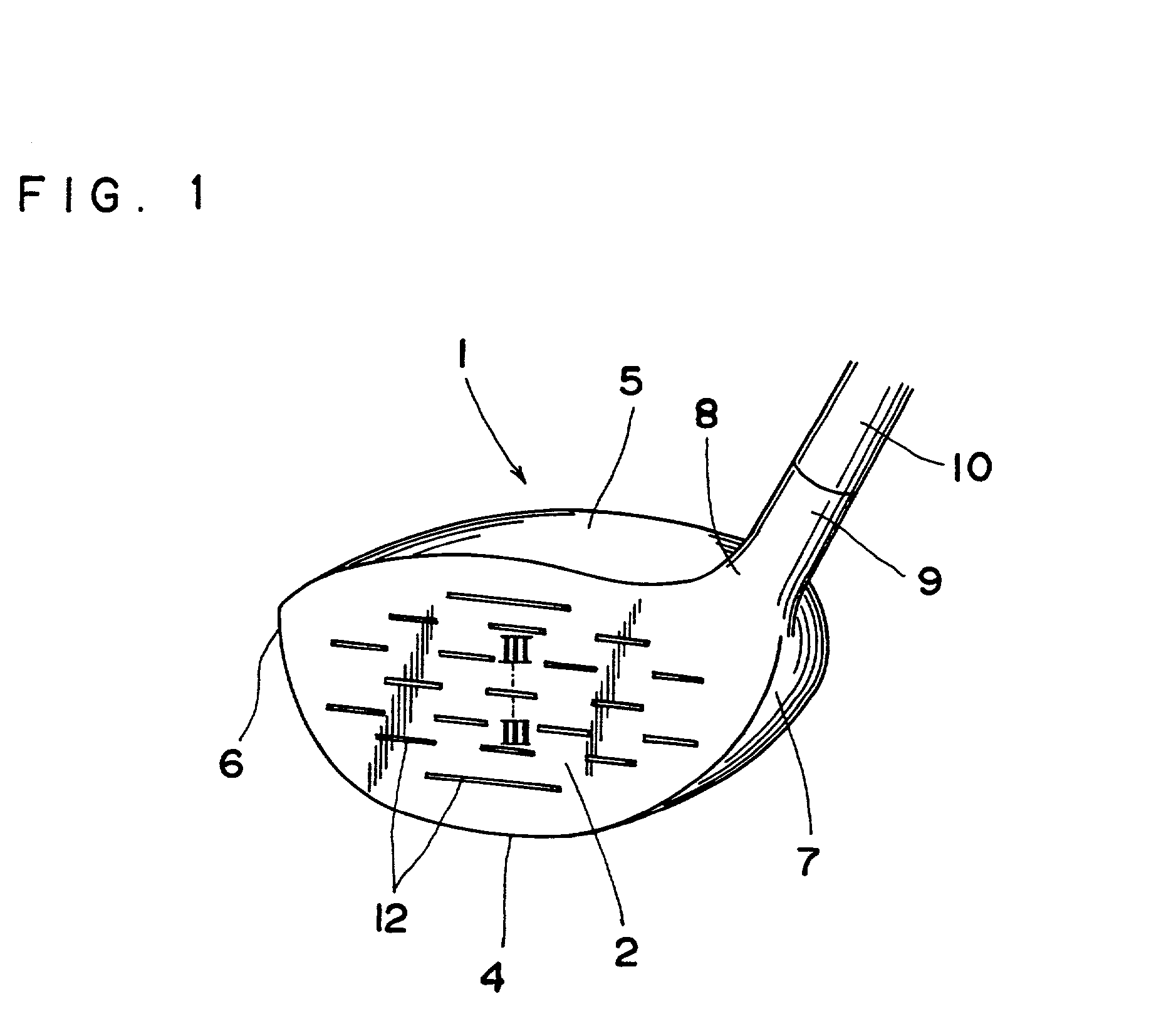
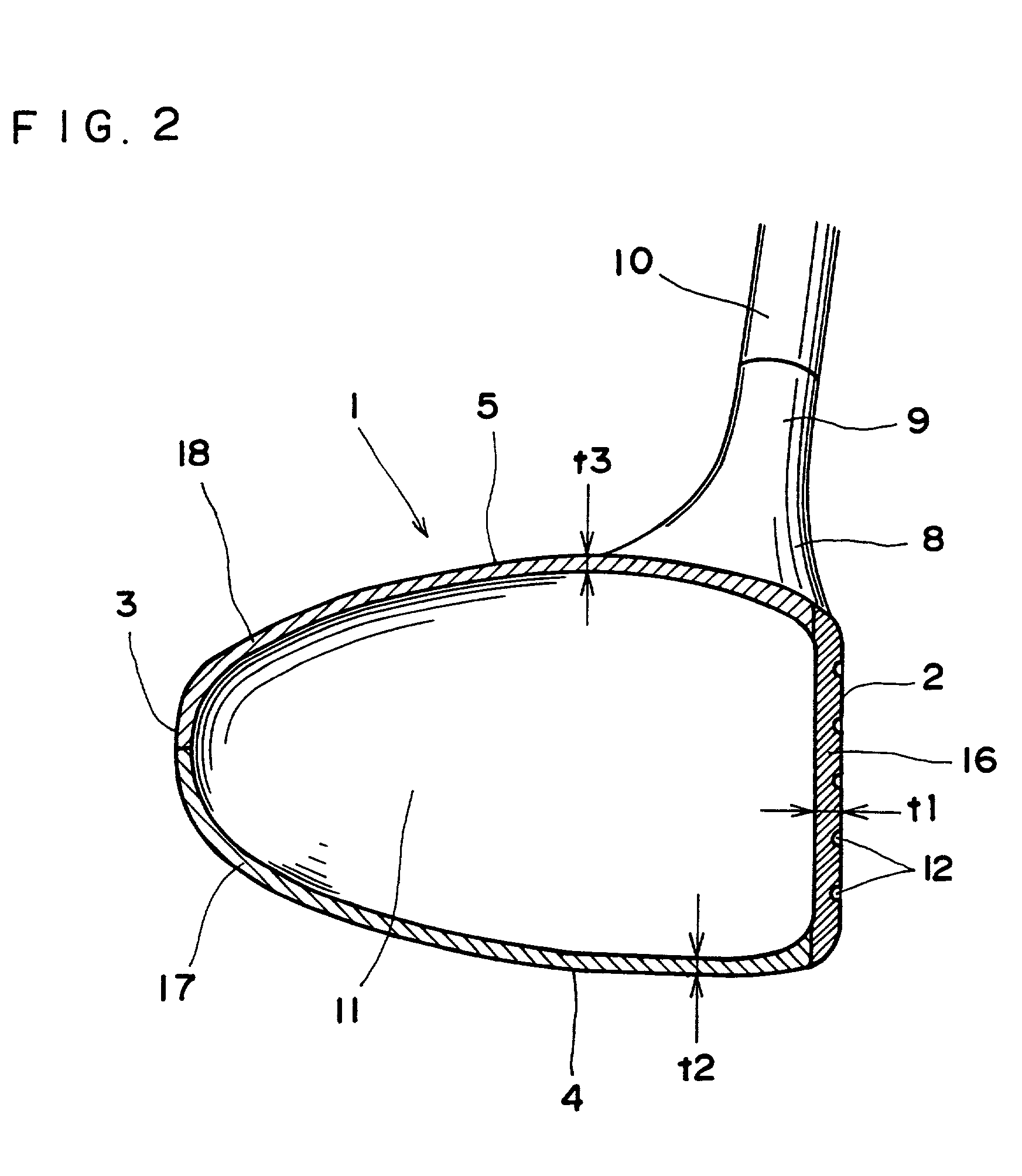
[0027] FIGS. 1 and 2 illustrate one example of a golf club in accordance with the invention. The golf club is a wood club, or a so-called metal wood with a metallic, hollow head 1. The head 1 comprises a face 2 for striking balls on a front face, a back 3 at a rear side, a sole 4 at a lower part, a crown 5 at a top part, a toe 6 at one side and a heel 7 at the other side, respectively. An upper part of the heel 7 is formed with a neck 8, from which extends a hose 19 upwardly. The hose 19 serves as a shaft connector for connecting a shaft 10 thereto. The head 1 has a hollow interior 11, which may be filled with suitable filler such as polyurethane. Further, the face 2 is formed with a plurality of grooves called score lines 12.

[0028] The head 1 is constructed of three shells, namely, a tabular face member 16, a body member 17 and a crown member 18 which construct the ...


PUM

PropertyMeasurementUnit
volumeaaaaaaaaaa
thicknessaaaaaaaaaa
thicknessaaaaaaaaaa

Abstract

A method for manufacturing a golf club with an improved durability which realizes so thin a club head that the head can be enlarged, suppressing the increase of the total weight. A cold rolled material, which is a beta type titanium alloy in a beta single phase and subjected to direct aging, is used for the head. Preferably, the material is subjected to at least 15% cold rolling reduction. The aging is able to improve durability and surface hardness. Due to the direct aging of the cold worked material without solution treatment, such a long time heat treatment is no longer necessary, thereby resulting in the reduction of production costs.

Description

CROSS REFERENCE TO RELATED APPLICATIONS[0001] This application is a continuation-in-part application of U.S. application Ser. No. 09 / 454,426 filed on Dec. 3, 1999, and now pending.BACKGROUND OF INVENTION[0002] 1. Field of the Invention[0003] The present invention relates to a method for manufacturing a golf club, particularly to a material used in the method.[0004] 2. Description of the Prior Art[0005] In a golf club head, one of means for enlarging the sweet area, i.e., an area on a face where a ball travels comparatively straight and well when struck thereon, is to large-size a club head itself. In recent years, some heads with more than 300 cc volume have come onto the market. Even if a club head is large-sized, yet the total weight thereof must be suppressed so as to ensure the easiness to handle. As a result, the head must be formed hollow inside, and its outer shells must be thinned. However, thinned outer shells generally lead to decreased strength of a club head, even to the...

Claims


Application Information

Patent Timeline
21 Feb 2002
Publication
US20020022534A1
IPC
A63B53/04
CPC
A63B53/0466; A63B2053/0416; A63B2053/0408; A63B53/047; A63B2209/00; A63B53/0408; A63B53/0416
Inventors
KOBAYASHI, KENJI; TSURUMAKI, MASAEI