Snowmobile engine mount

a technology for engine mounts and snowmobiles, applied in snowmobiles, jet propulsion mounting, cycles, etc., can solve the problems of large vibration, engine mounts that require relatively large amounts of space within the chassis, and conventional engine mounts that require more space in the chassis

Inactive Publication Date: 2002-03-14
BOMBARDIER RECREATIONAL PROD INC
View PDF0 Cites 23 Cited by
  • Summary
  • Abstract
  • Description
  • Claims
  • Application Information

AI Technical Summary

Benefits of technology

[0010] Yet a further object of the invention is to provide an engine mount for a vehicle that can be installed and access from the sides of the vehicle to simplify production on an assembly line.

Problems solved by technology

Typically, a snowmobile is powered by a two-stroke engine, which can cause large amounts of vibration.
However, such conventional engine mounts required relatively large amounts of space within the chassis for the engine and to provide the space needed to position the adjustable dampers.
Also, conventional engine mounts require more space in the chassis at the front and rear of the engine.
Further, previous engine mount dampers were designed to work most effectively against movement of the engine in the direction of movement of the vehicle and in the direction of the height of the vehicle, which in some situations is not the preferred direction for accommodating and damping forces such movements generate.

Method used


Image

  • Snowmobile engine mount
  • Snowmobile engine mount
  • Snowmobile engine mount

Examples


Embodiment Construction

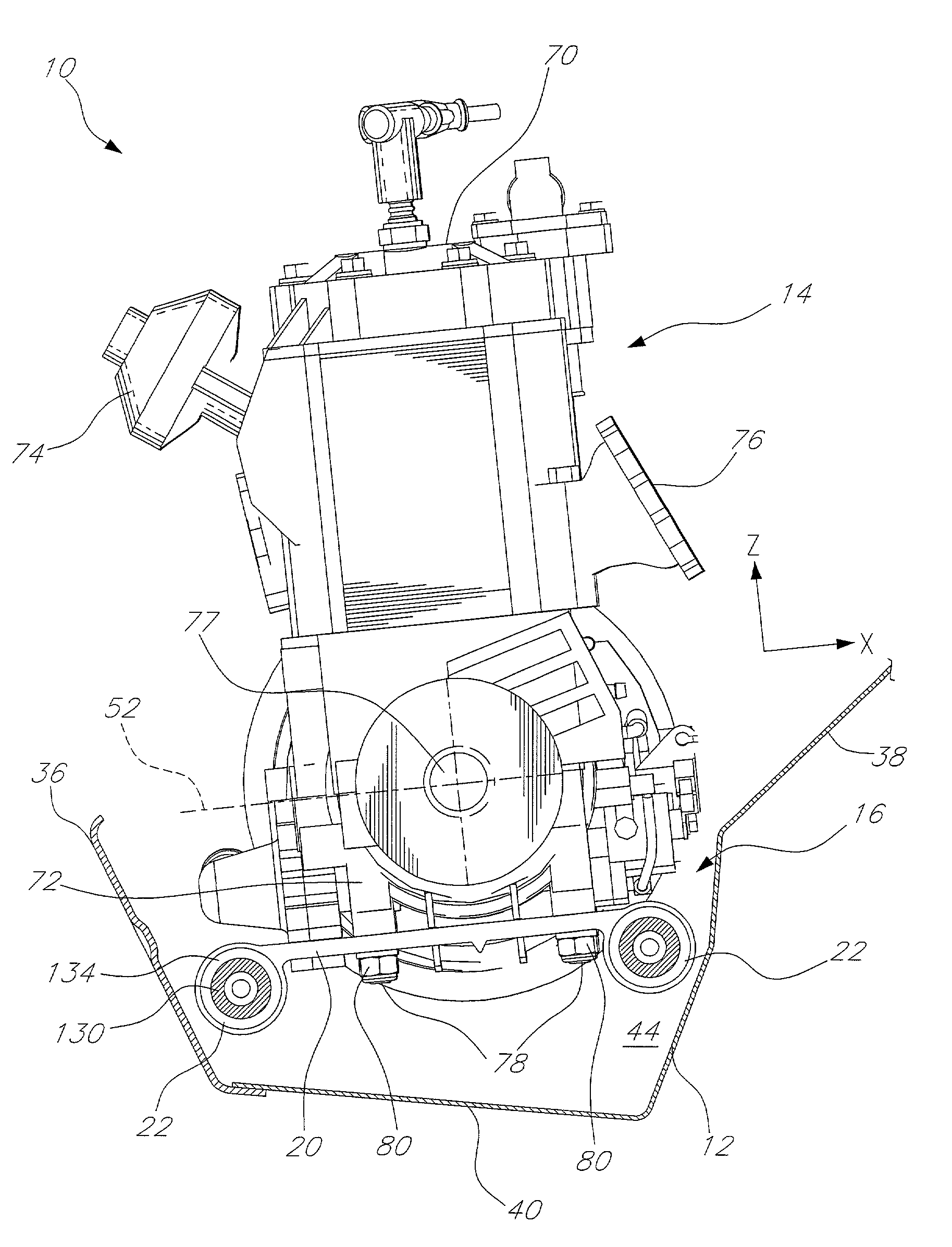
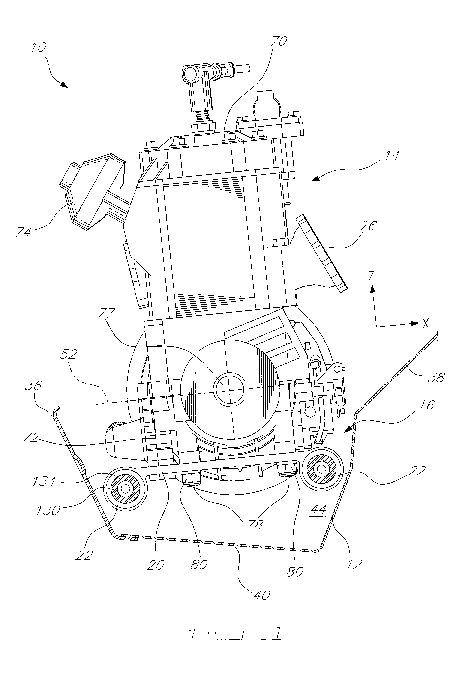
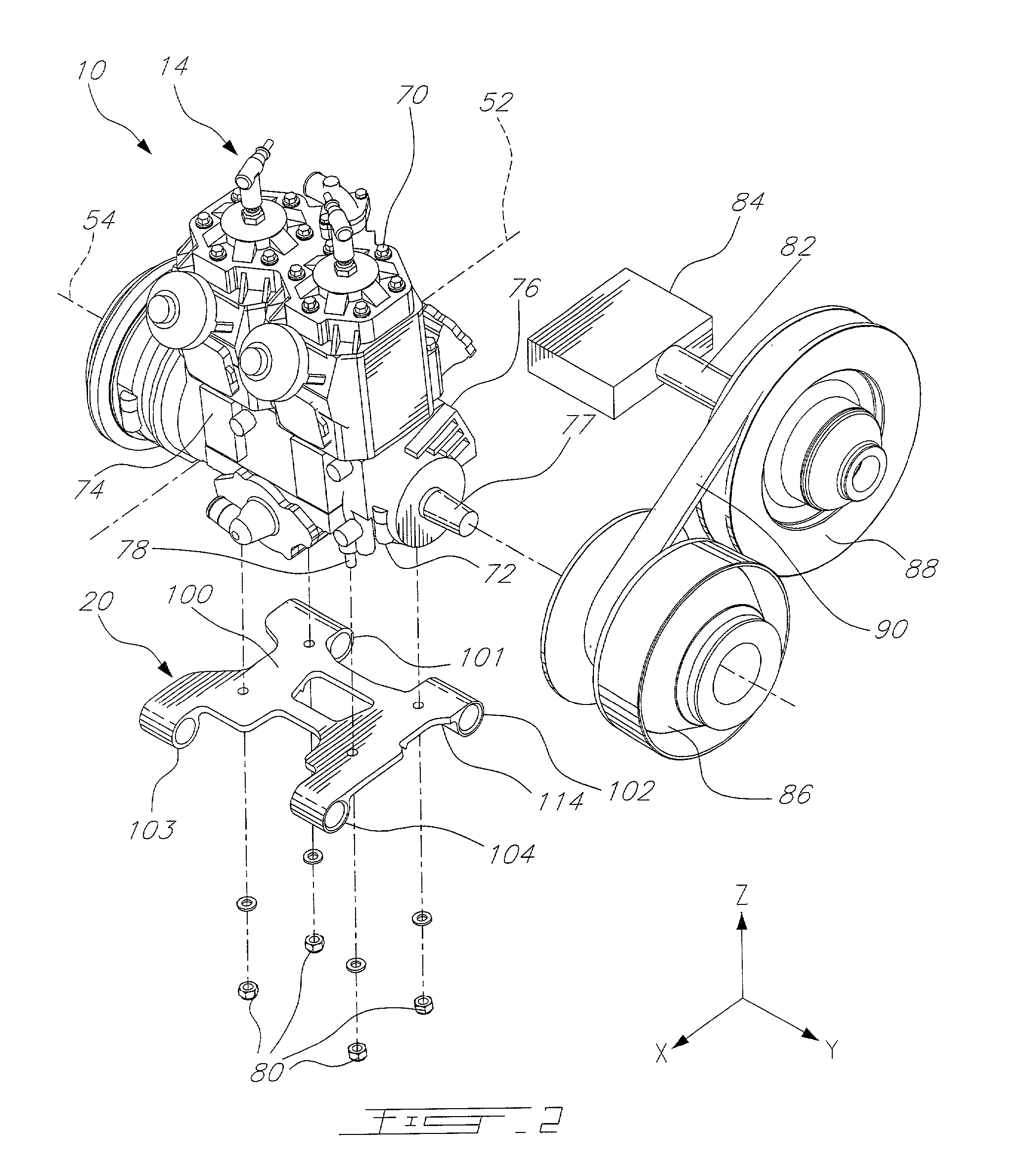
[0034] As seen in FIGS. 1-4, a portion of a vehicle 10, such as a snowmobile, is illustrated, including a section of a chassis 12, an engine 14, and an engine mount 16 coupling the engine 14 to the chassis 12. The engine mount 16 both secures the engine 14 to the chassis 12 and damps vibration generated by the engine 14. The goal is to have the amount of vibration transferred from the engine 14 to the chassis 12 reduced to acceptable levels. The engine mount can include a base plate 20 and damping mounts 22.

[0035] Although engine mount 16 is described herein with respect to a snowmobile, it should be understood that engine mount 16 can be used with other vehicles where engines are mounted, as well as with non-vehicle equipment having an engine. Also, although engine mount 16 is described as supporting an engine, the engine mount 16 can be used to support other devices other than engines, especially if there exists a need to reduce vibration between the supported part and another par...


PUM


Abstract

An engine mount for a vehicle, such as a snowmobile, that can be used when space for the engine within a chassis is limited and which is easily accessed from the side of the chassis for assembly and repair. The engine mount can be attached to the bottom of an engine that is positioned within a chassis. The engine mount can include four hollow, cylindrical portions. Each cylindrical portion having an axis extending transverse to the longitudinal direction of the snowmobile chassis and receiving a damping mount. Fasteners can be inserted through the chassis to couple with the damping mounts and cylindrical portions in a direction that is transverse to the longitudinal direction of the chassis. The configuration of the damping mounts permits effective damping especially in a direction transverse to the direction of forward travel of the vehicle.

Description

[0001] This application claims the benefit of priority to U.S. patent application Ser. No. 60 / 245,675, filed Nov. 6, 2000, the contents of which are herein incorporated by reference. This application is also related to U.S. patent application Ser. No. 09 / 472,134 for a SNOWMOBILE, filed Dec. 23, 1999; to U.S. patent application Ser. No. 60 / 167,614 for a SNOWMOBILE, filed Nov. 26, 1999; and U.S. patent application Ser. No. 60 / 230,432 for a A NOVEL THREE WHEEL VEHICLE, filed Sep. 6, 2000, the contents of each being incorporated herein by reference.[0002] 1. Field of the Invention[0003] The present invention relates generally to supporting elements within a vehicle. More specifically, the invention relates to a support for a vehicle engine.[0004] 2. Background of the Invention[0005] Typically, a snowmobile is powered by a two-stroke engine, which can cause large amounts of vibration. In order to decrease the amount of vibration from the engine to the chassis, typically, such engines wer...

Claims


Application Information

Patent Timeline
Patent Type & Authority Applications(United States)
IPC IPC(8): B60K5/12
CPCB60K5/12B60K5/1208B60K5/1216B60Y2200/252
Inventor FOURNIER, ANDRELEFEBVRE, MICHEL
Owner BOMBARDIER RECREATIONAL PROD INC
Why Eureka
Try Eureka