Method and apparatus for controlling AC pulse arc welding and welding power source apparatus

Inactive Publication Date: 2002-03-14
DAIHEN CORP
View PDF0 Cites 41 Cited by
  • Summary
  • Abstract
  • Description
  • Claims
  • Application Information

AI Technical Summary

Problems solved by technology

As described above, accompanying with the droplet transfer at the time of polarity switching, a large amount of expulsion is scattered and adheres to the welding bead

Method used


Image

  • Method and apparatus for controlling AC pulse arc welding and welding power source apparatus
  • Method and apparatus for controlling AC pulse arc welding and welding power source apparatus
  • Method and apparatus for controlling AC pulse arc welding and welding power source apparatus

Examples


Embodiment Construction

[0174] FIG. 15 is a timing chart of signals showing an operation of a method for controlling AC pulse arc welding according to a modified first preferred embodiment of the present invention, wherein FIG. 15(A) shows a welding current Iw, and FIG. 15(B) shows a welding voltage Vw.

[0175] The modified first preferred embodiment is a modification of the first preferred embodiment shown in FIG. 6. Referring to FIG. 15, the switching current Ic for the switching current interval Tc may be gradually increased with a positive inclination as the time elapses so that the switching current Ic is smaller than the threshold current for droplet transfer.

[0176] FIG. 16 is a timing chart of signals showing an operation of a method for controlling AC pulse arc welding according to a modified fourth preferred embodiment of the present invention, wherein FIG. 16(A) shows a welding current Iw, and FIG. 16(B) shows a welding voltage Vw.

[0177] The modified fourth preferred embodiment is a modification of...


PUM

PropertyMeasurementUnit
Timeaaaaaaaaaa
Timeaaaaaaaaaa
Timeaaaaaaaaaa

Abstract

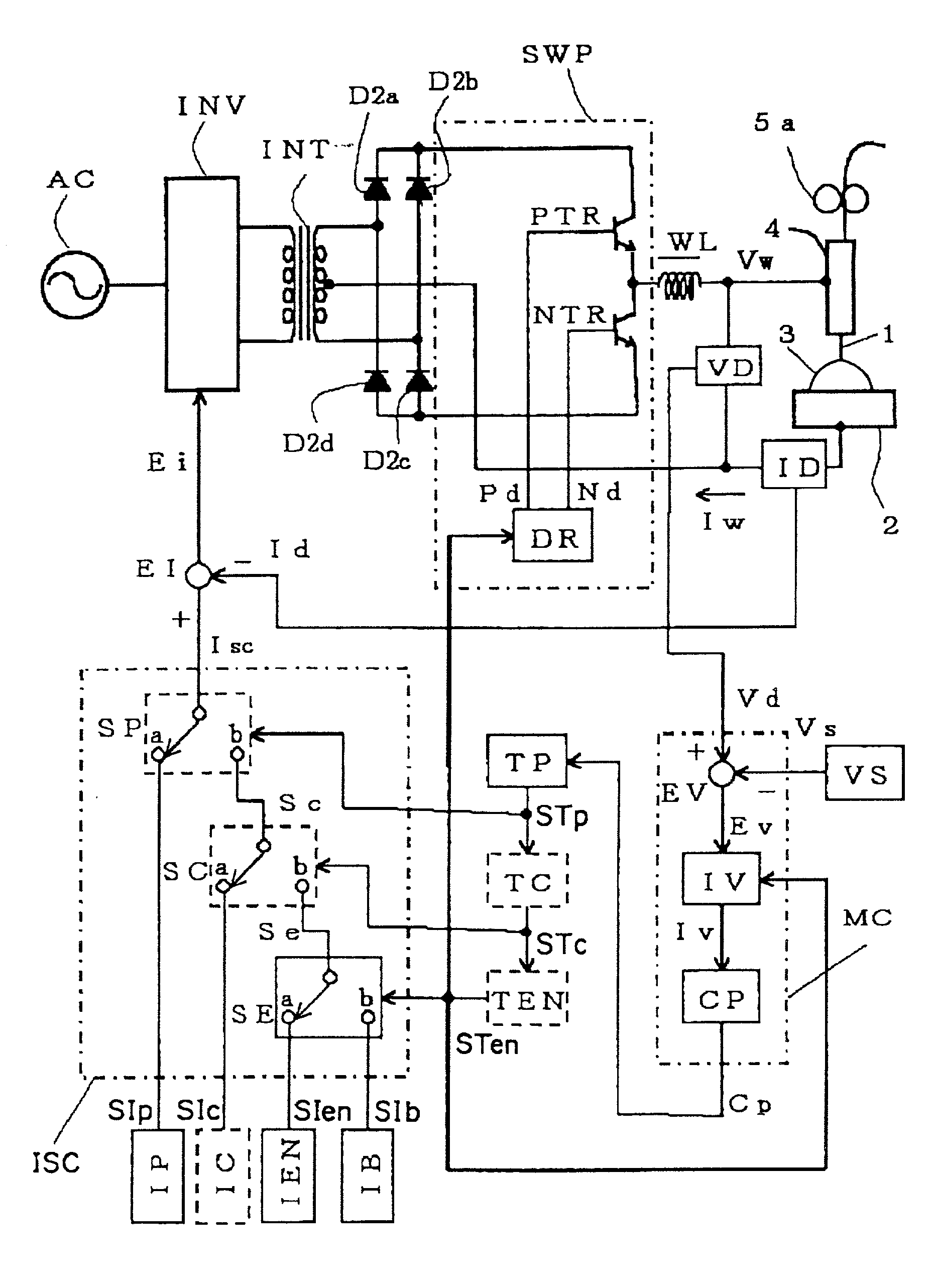
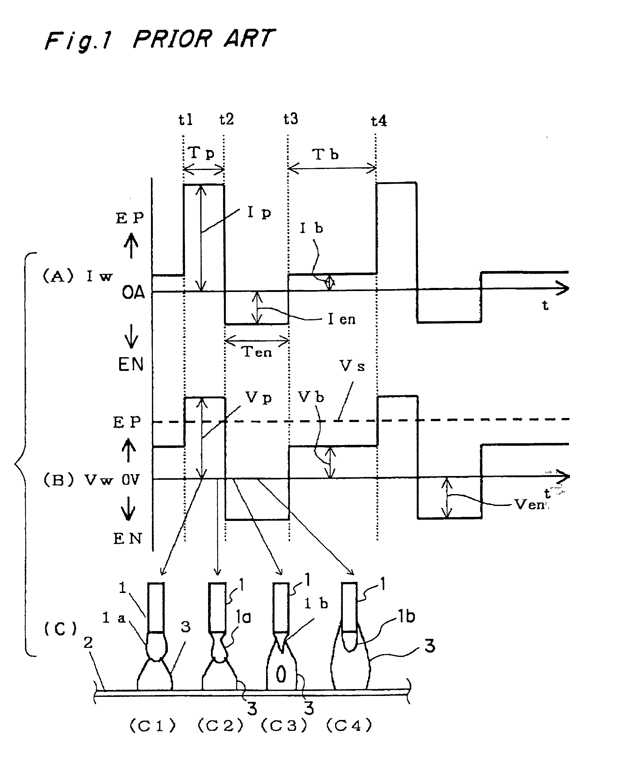
In a method and an apparatus for controlling AC pulse arc welding executed by supplying a welding current flowing between a welding wire and an object to be welded with feeding the welding wire at a feeding speed corresponding to a predetermined feeding speed setting signal, a one-period process for supplying the welding current is repeatedly executed. The one-period process includes a first process during a peak time interval, a second process during a negative electrode time interval, and a third process during a base time interval. The one-period process further includes a fourth process during a switching current interval, inserted between the peak time interval and the negative electrode time interval, for supplying a welding current having a switching current for stopping growth of droplet which is smaller than a threshold current with a positive electrode polarity.

Description

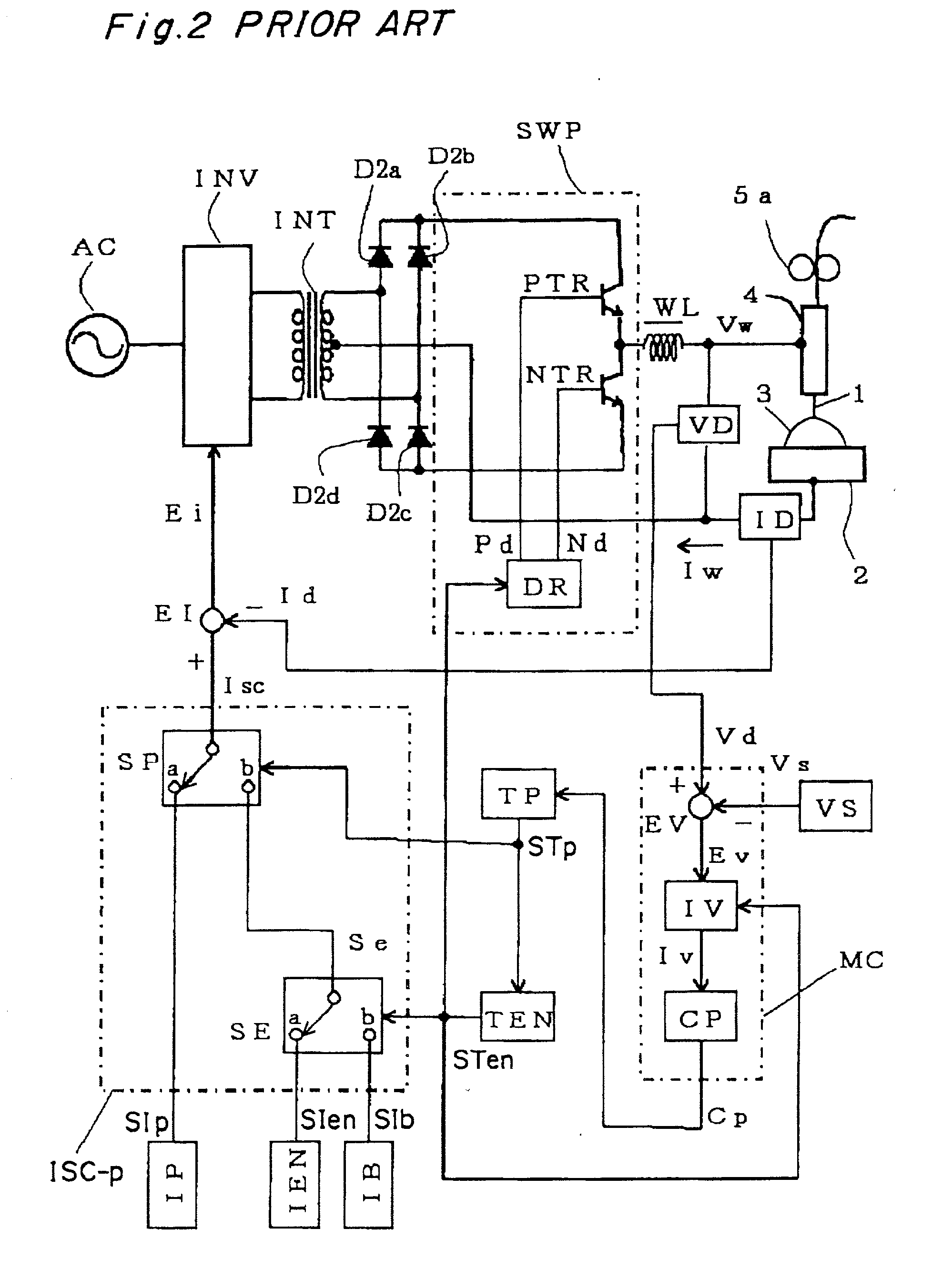
[0001] 1. Field of the Invention[0002] The present invention relates to a method and an apparatus for controlling AC (Alternating Current) pulse arc welding, and a welding power source apparatus, and in particular, to a method and an apparatus for controlling consumable electrode type AC pulse arc welding, and a welding power source apparatus for use in consumable electrode type AC pulse arc welding.[0003] 2. Description of the Prior Art[0004] In an AC pulse arc welding method which is executed by supplying a welding current Iw flowing between a welding wire and an object to be welded with feeding the welding wire at a feeding speed, a one-period process for supplying the welding current is repeatedly executed where the one-period process including:[0005] (a) a first process during a peak time interval Tp for supplying a welding current Iw having a peak current Ip for causing droplet transfer, which is larger than a predetermined threshold current (or critical current) and which flo...

Claims


Application Information

Patent Timeline
IPC IPC(8): B23K9/09B23K9/073B23K9/12
CPCB23K9/09B23K9/092B23K9/093B23K9/124B23K9/125
Inventor TONG, HONGJUN
Owner DAIHEN CORP
Why Eureka
Try Eureka