Plasma furnace disposal of hazardous wastes

Inactive Publication Date: 2002-04-11
RES TRIANGLE INST
View PDF0 Cites 29 Cited by
  • Summary
  • Abstract
  • Description
  • Claims
  • Application Information

AI Technical Summary

Benefits of technology

0022] Yet, another object of the invention is to provide a rf power supply tolerant of dynamic load changes presented by a plasma in the apparatus for plasma disposal such that parasitic energies in the rf power supply do not destabilize the rf power supply.
0023] These and other objects are achieved according to the present invention by providing a novel method and apparatus for plasma waste disposal of hazardous waste material, where the hazardous material is volatilized under vacuum inside a containment chamber to produce a pre-processed gas as input to a plasma furnace including a plasma-forming region in which a plasma-forming magnetic field is produced. The pre-processed gas is passed at low pressure and without circumvention through the plasma-forming region and is directly energized to an inductively coupled plasma state such that hazardous

Problems solved by technology

Given that many of neurological bio-hazards, such as sarin are in liquid form, this presents significant complication.
For example, processes which might be used on solid waste such as simple closed containment heating to 540.degree. C., if used will create extreme pressures.
This scenario presents an unacceptable risk to the environment and personnel at disposal sites.
Effluent from these drums is no longer pure, rather the effluent will contain significant amounts of water vapor and hydrocarbons.
In addition, the articles packed in the drums have a variety of shapes and compositions which presents gas stratification problems with different components volatilizing in the drum at different depths in the drum.
Unfortunately, incineration techniques produce considerable exhaust to the atmosphere which poses significant safety concerns given that 100% destruction of the hazardous nerve gas agents may not be certain.
This redundancy adds to the cost of the facility and its operation.
Despite the remote location, the incineration facility still attracts a significant amount of public scrutiny and watch-dogging.
In addition, it is politically unacceptable to permit shipment of loads of nerve gas agents across the country to central disposal facilities.
Furthermore, establishing incineration systems at a multitude of storage sites (many which are closer to larger population concentrations) is financially and politically unacceptable.
Accidental discoveries of chemical waste material by the public have demonstrated the seriousness of the buried weapons problem.
The concentrations of sarin in these drums vary significantly from one drum to another, and in addition many drums are contaminated with water.
While these approaches have been shown to be effective in converting toxic agents, they too suffer with similar problems to the combustion processes.
Unfortunately, the low power level limits the quantity of hazardous waste products which can be converted on a single pass.
One can see from the calculation that low-power, glow-discharge plasma systems typically 100- 3000 W are limited in the quantity of nerve gas agent which can be throughput.
Input power to glow discharge systems can not be raised to high power levels.
Glow discharge systems have inherent limitations which restrict operation at higher powers.
Continued operation in this mode significantly degrades the electrode material.
However, this approach suffers from severe plasma non-uniformities.
Thus, gas b

Method used


Image

  • Plasma furnace disposal of hazardous wastes
  • Plasma furnace disposal of hazardous wastes
  • Plasma furnace disposal of hazardous wastes

Examples


Example

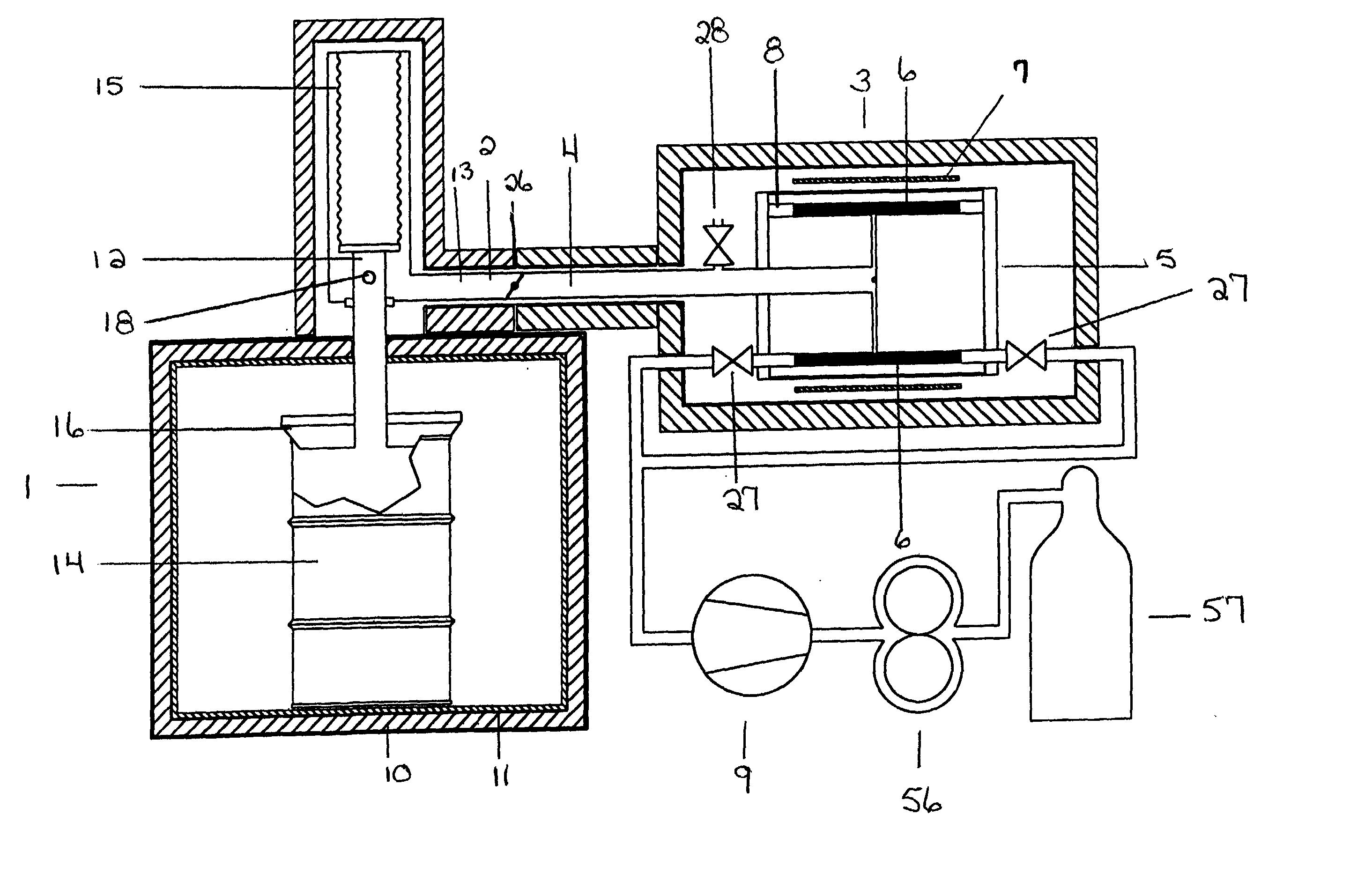
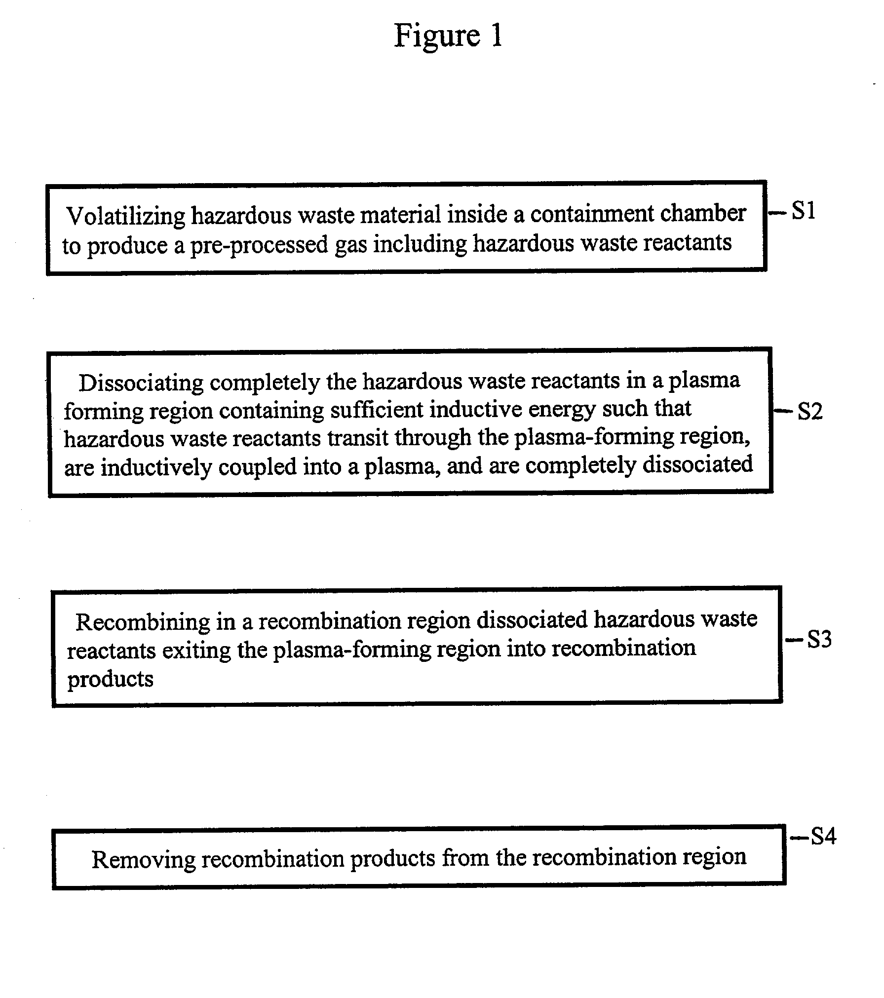
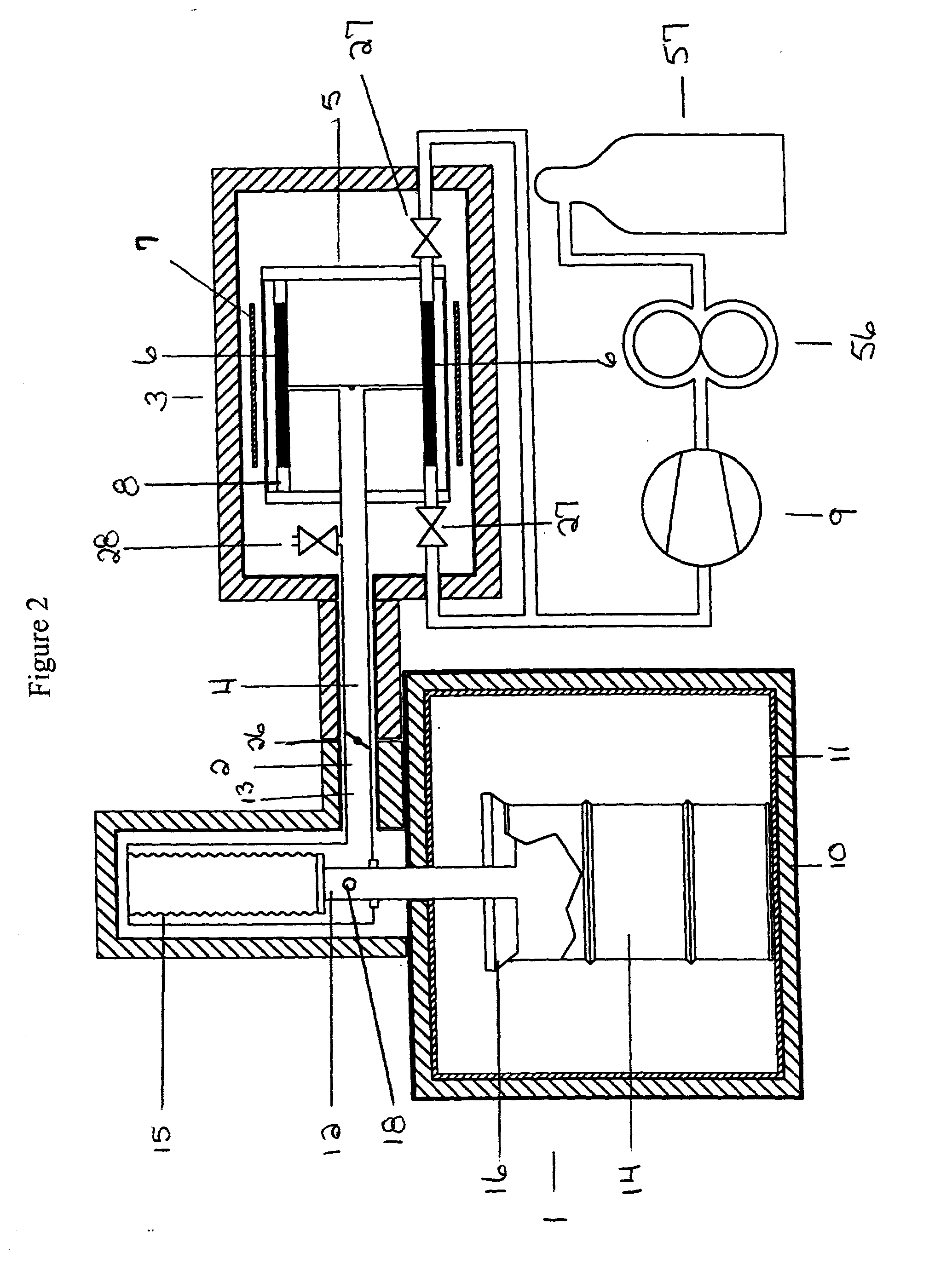
[0044] Referring now to the drawings, wherein like reference numerals designate identical or corresponding parts throughout the several views, and more particularly to FIG. 1 thereof, is a flow chart showing the method of the plasma waste disposal. The method comprises the steps of: volatilizing in S1 at sub-atmospheric pressure hazardous waste material in a containment chamber to produce a pre-processed gas including hazardous waste reactants; dissociating completely in S2 the hazardous waste reactants from the containment chamber in a plasma-forming region containing sufficient inductive energy such that said hazardous waste reactants transit through the plasma-forming region, are inductively coupled into a plasma having a magnetic skin depth, and are completely dissociated; recombining in S3 in a recombination region dissociated hazardous waste reactants exiting the plasma-forming region as recombination products, and removing in S4 recombination products from said recombination ...


PUM

PropertyMeasurementUnit
Timeaaaaaaaaaa
Pressureaaaaaaaaaa
Electric chargeaaaaaaaaaa

Abstract

A method and apparatus for plasma waste disposal of hazardous waste material, where the hazardous material is volatilized under vacuum inside a containment chamber to produce a pre-processed gas as input to a plasma furnace including a plasma-forming region in which a plasma-forming magnetic field is produced. The pre-processed gas is passed at low pressure and without circumvention through the plasma-forming region and is directly energized to an inductively coupled plasma state such that hazardous waste reactants included in the pre-processed gas are completely dissociated in transit through the plasma-forming region. Preferably, the plasma-forming region is shaped as a vacuum annulus and is dimensioned such that there is no bypass by which hazardous waste reactants in the pre-processed gas can circumvent the plasma-forming region. The plasma furnace is powered by a high frequency power supply outputting power at a fundamental frequency. The power supply contains parasitic power dissipation mechanisms to prevent non-fundamental, parasitic frequencies from destabilizing the fundamental frequency output power. These power loss mechanisms use either distributed resistance or frequency-selective power-loss devices to prevent parasitic oscillations from instantaneously turning on the high frequency power oscillator at non-fundamental frequencies.

Description

BACKGROUND OF THE INVENTION[0001] 1. Field of the Invention[0002] The present invention relates to a method and apparatus for plasma furnace disposal of hazardous wastes.[0003] 2. Discussion of the Background[0004] In the field of chemical waste disposal, there are a number of complicating technical and legal requirements which must be managed. For example, as the government designated operational authority in all matters related to chemical weapons disposal, the Army requires that nerve-gas contaminated solid waste material which is disposed from its possession must be certified to have met a 5X standard which requires that the material has been to 540.degree. C. for 15 min. Given that many of neurological bio-hazards, such as sarin are in liquid form, this presents significant complication. For example, processes which might be used on solid waste such as simple closed containment heating to 540.degree. C., if used will create extreme pressures. A container filled with sarin will ...

Claims


Application Information

Patent Timeline
IPC IPC(8): H05H1/46
CPCY10S588/90H05H1/46
Inventor MARKUNAS, ROBERT J.POSTHILL, JOHN B.HENDRY, ROBERT C.THOMAS, RAYMOND
Owner RES TRIANGLE INST
Why Eureka
Try Eureka