Pulley having progressively variable sheave angle

a technology of progressively variable sheave angle and belt, which is applied in the direction of driving belts, v-belts, portable lifting, etc., can solve the problems of reducing the efficiency of belts, reducing the life of belts, and widening belts

Inactive Publication Date: 2002-04-11
BOMBARDIER RECREATIONAL PROD INC
View PDF0 Cites 23 Cited by
  • Summary
  • Abstract
  • Description
  • Claims
  • Application Information

AI Technical Summary

Problems solved by technology

In such constant variable transmissions, belt life has been a problem, especially for consumers, because the stress experienced by the belts can cause failure.
However, wider belts create higher power losses because the inside of the belt deforms.
Also, the centrifugal force on thicker belts is higher, and more heat is generated during operation thus decreasing the efficiency of the belt.
The disadvantage in this case is the change in angle

Method used


Image

  • Pulley having progressively variable sheave angle
  • Pulley having progressively variable sheave angle
  • Pulley having progressively variable sheave angle

Examples


Embodiment Construction

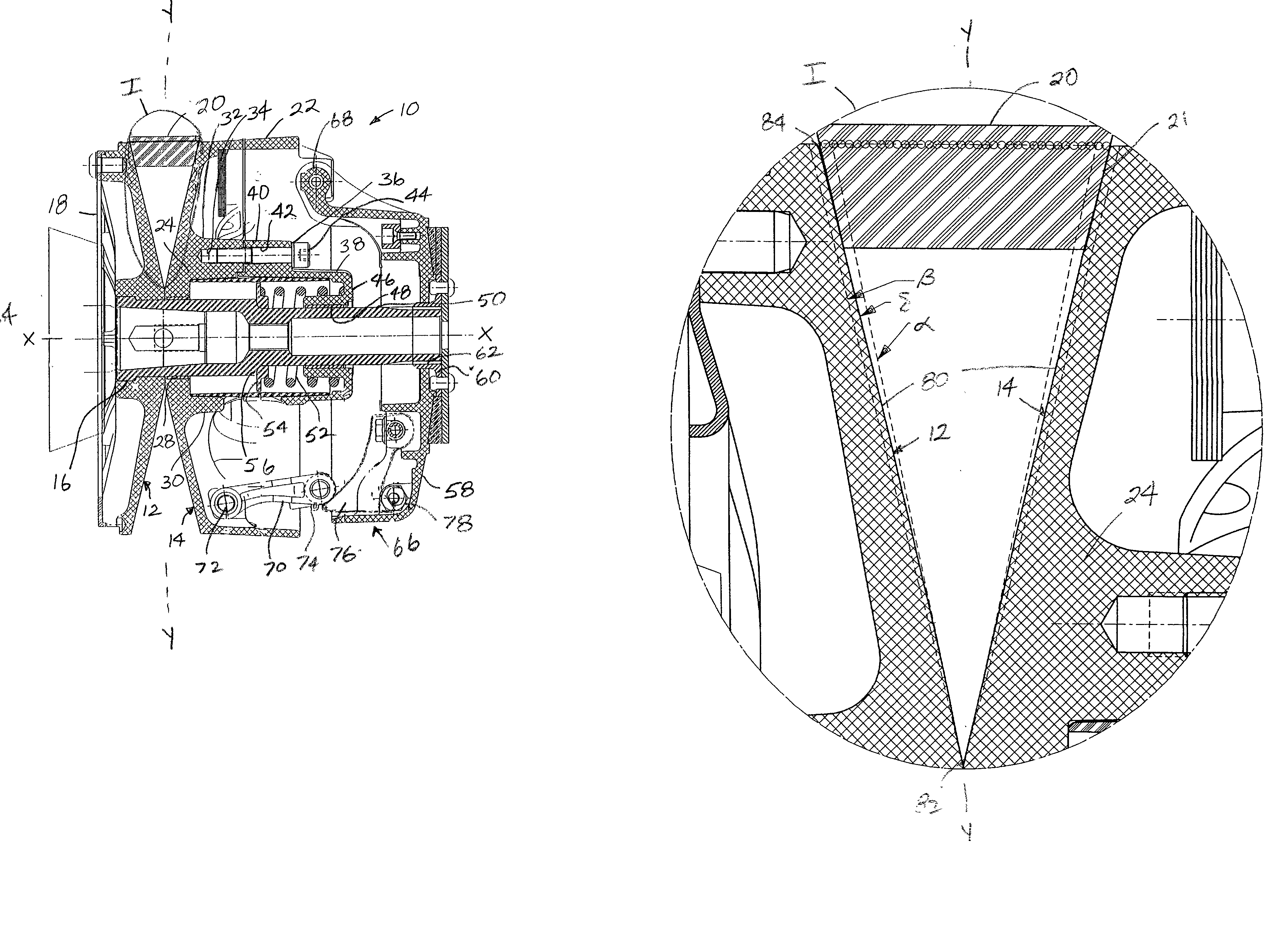
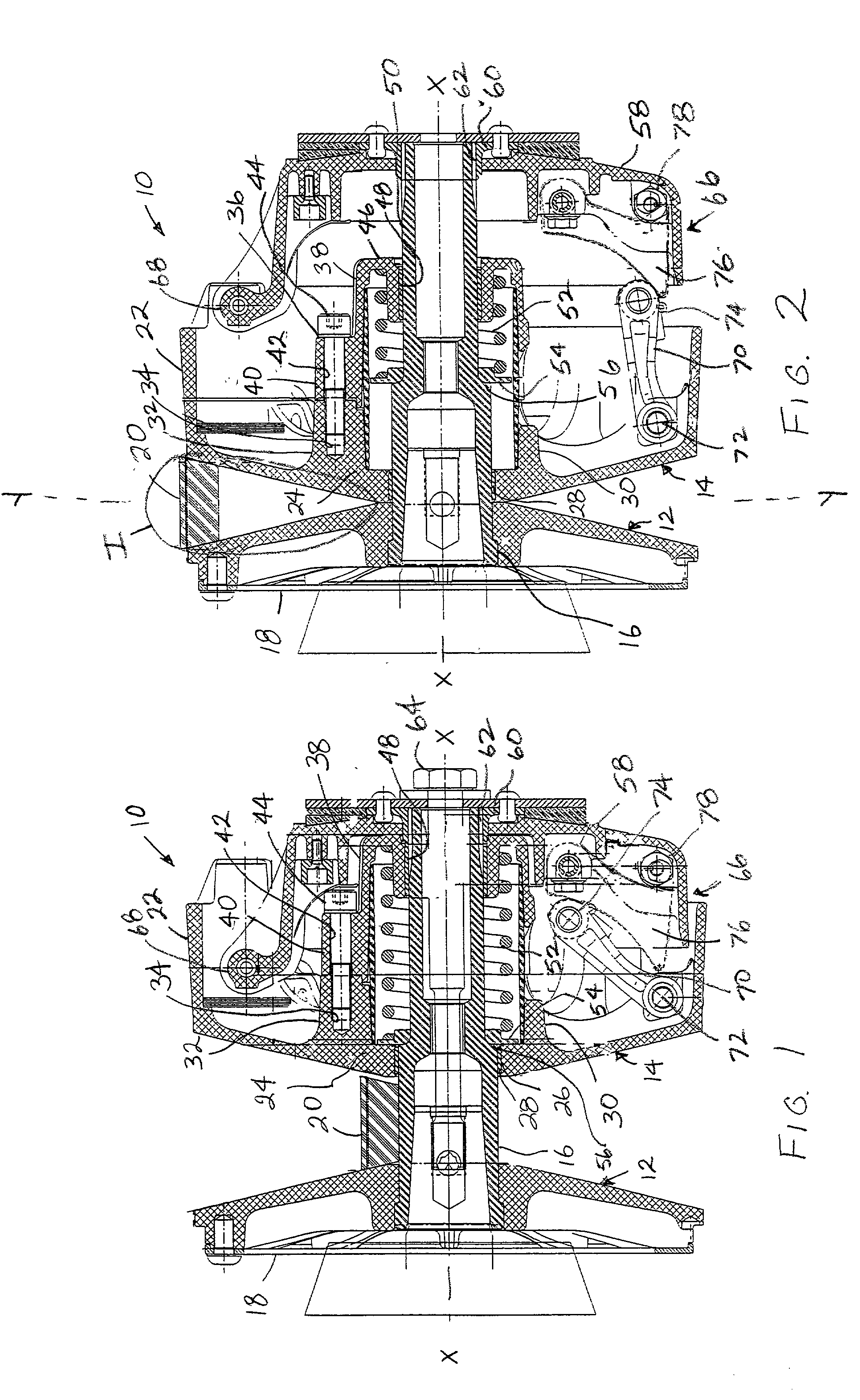
[0028] The pulley system in accordance with the invention is described in use with a constant variable transmission (CVT) for purposes of illustration. However, it is understood that the progressively angled sheave of this invention can be used in any suitable drive system. Further, it is noted that the pulley system, and particularly the sheave, described herein according to embodiments of this invention can be applied to a drive and / or driven clutch of a CVT and can be applied in various transmissions, especially vehicle transmissions used in snowmobiles, all terrain vehicles, automobiles and the like.

[0029] As shown in FIGS. 1 and 2, the variable ratio drive pulley assembly 10 includes two sheaves in the form of two frusto-conical flanges 12 and 14 co-axially arranged with respect to a drive shaft 16. Drive shaft 16 is adapted to be attached to an output shaft of an engine, for example, a snowmobile engine. Both flanges 12 and 14 are supported to rotate with shaft 16 about axis X...


PUM


Abstract

A pulley system for use in a constant variable transmission includes a pair of pulley sheaves or flanges mechanically linked by a belt so that the outer surfaces of the belt interact with the inner surfaces of the flanges. At least one of the pulley flanges has an inclined inner surface disposed at an angle that changes progressively based on a curve have a variable radius. For example, the sheave angle can change progressively from 9 degrees to 12 degrees or from 12 degrees to 14 degrees, with no sharp or stepped edges. The belt can have a complementary angled surface also. The progressively variable angle allows the flange surface to more closely match the side surface of the belt, which can increase the belt life be reducing stress experienced by the belt. The pulley system is useable in a transmission for a vehicle, for example a snowmobile or an all terrain vehicle.

Description

[0001] 1. Field of the Invention[0002] The invention relates to a pulley system for use in a transmission, particularly a constant variable transmission. The invention more specifically relates to the pulley flange, also known as a sheave, and belt in such a pulley system.[0003] 2. Description of the Related Art[0004] Variable ratio drive pulleys, which are known, are generally employed to transmit a drive force from an engine via a belt transmission to a driving mechanism. Typical pulley systems comprise a pair of opposed frusto-conical flanges or sheaves mounted on the output shaft of the engine and arranged to apply a drive to an endless flexible belt positioned between the flanges. Both flanges rotate with the output shaft, one flange being axially fixed, and the other flange being axially shiftable towards and away from the fixed flange. A mechanism is generally provided to urge the movable flange away from the fixed flange so that at idling or low engine speeds there is no dri...

Claims


Application Information

Patent Timeline
IPC IPC(8): F16H55/56F16H61/662
CPCF16H55/56F16H9/125
Inventor AITCIN, XAVIER-PIERRE
Owner BOMBARDIER RECREATIONAL PROD INC
Why Eureka
Try Eureka