Current-steering D/A converter and unit cell

a converter and current-steering technology, applied in the direction of code conversion, pulse technique, instruments, etc., can solve the problems of large layout area, waste of chip space, and inconvenient operation of structure in fig. 3(b)

Inactive Publication Date: 2002-04-18
SILICON INTEGRATED SYSTEMS
View PDF0 Cites 45 Cited by
  • Summary
  • Abstract
  • Description
  • Claims
  • Application Information

AI Technical Summary

Problems solved by technology

Likewise, the structure in FIG. 3(b) is not suitable for operating at low power voltages.
Although this method is more convenient than the prior art technologies, but creates a disadvantage of occupying a large layout area.
It is obvious that the structure in FIG. 3(c) will waste a lot of chip area.

Method used


Image

  • Current-steering D/A converter and unit cell
  • Current-steering D/A converter and unit cell
  • Current-steering D/A converter and unit cell

Examples


Embodiment Construction

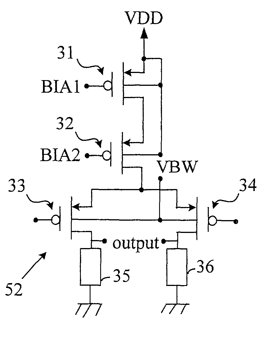
[0032] The present invention does not limited restrict to any kind of transistors, but is most suitable to PMOS transistors. Therefore, PMOS transistors are taken as an example in the following embodiments.

[0033] FIG. 5 shows a schematic diagram of a controllable current switches module of a current-steering D / A converter according to the present invention. The controllable current switches module 12 of the present invention comprises a plurality of unit cells 52, which receives bias voltages BIA1 and BIA2 (provided that there are two cascode-connected transistors, and the number of bias voltage is proportional to the number of cascode-connected transistors) generated by the current reference generating module 11 and a second bias voltage VBW for independently controlling the n-well region, and the plurality of unit cells accumulates their respective output currents as I.sub.O.

[0034] FIGS. 6(a) to 6(d) show schematic diagrams of current-steering D / A unit cells according to the prese...


PUM


Abstract

The present invention discloses a current-steering digital-to-analog converter and unit cells. The present invention proposes an n-well bias control circuit for generating a bias voltage whose magnitude is less than the power voltage, therefore the body effect of the transistors could be reduced. Relatively, the threshold voltage and VGS would be reduced. Therefore, even in a low-voltage operation, each transistor could be operated normally in the saturation region. Besides, the plurality of pairs of current switches could be implemented in the same n-well region, instead of being implemented in different n-well regions with leaving a space among each other. Finally, the chip area would be reduced.

Description

[0001] 1. Field of the Invention[0002] The present invention relates to a current-steering D / A converter and unit cell, and particularly to a current-steering D / A converter and unit cell which can operate at low voltages and occupy less areas.[0003] 2. Description of Related Art[0004] A current-steering D / A converter is usually used in signal processing. For example, a graphic chip uses three current-steering D / A converters to transform red, blue and green digital video signals to analog video signals.[0005] FIG. 1 shows a prior art current-steering D / A converter. The currentsteering D / A converter 10 comprises a current reference generating module 11, a controllable current switching module 12 and a current-to-voltage converting module 13. The current reference generating module 11 utilizes the characteristic of virtual short of an operational amplifier 14 to transfer a positive-end voltage V.sub.ref to a negative end. Relatively, the current Iref flowing through a resistor 17 is eq...

Claims


Application Information

Patent Timeline
Patent Type & Authority Applications(United States)
IPC IPC(8): H03K17/041H03K17/16H03K17/693H03M1/74
CPCH03K17/04106H03K17/162H03M1/742H03K2217/0018H03K17/693
Inventor YAO, CHI-TAISHEN, WEI-CHENLIU, HUNG CHIH
Owner SILICON INTEGRATED SYSTEMS
Why Eureka
Try Eureka