Paint brush cleaning device

a cleaning device and paint brush technology, applied in carpet cleaners, vehicle cleaning, bowling games, etc., can solve the problems that none of such devices provide means useful in removing paint from paintbrush bristles and heels, and achieve the effect of effectively cleaning commercial paintbrushes, effectively cleaning paintbrushes, and effective cleaning of oil-based and water-based paints

Inactive Publication Date: 2002-05-02
BRACKETT TED J +1
View PDF0 Cites 30 Cited by
  • Summary
  • Abstract
  • Description
  • Claims
  • Application Information

AI Technical Summary

Benefits of technology

0016] It is an object of the present invention to provide an apparatus that effectively cleans paintbrushes of oil-bases and water-based paints. It is a further object of this invention to provide an apparatus that can clean a single paintbrush or simultaneously cleans a plurality of paintbrushes. It is also an object of this invention to provide an apparatus that effectively cleans commercial paintbrushes within approximately ninety seconds. It is a further objective of this invention to provide a paintbrush cleaning apparatus that can be used automatically or semi-automatically. It is another objective of this invention to provide a paintbrush cleaning apparatus that effectively cleans paintbrushes without damaging the bristles or other parts of the brushes so that the paintbrushes may be repeatedly re-used and maintained in good condition for an extended period of time. It is another object of this invention to provide a mobile apparatus for cleaning paintbrushes. It is a further object of this invention to provide an apparatus for cleaning paintbrushes that includes a means of drying the cleaned paintbrushes.

Problems solved by technology

None of such devices provide means useful in removing paint from paintbrush bristles and heels.

Method used


Image

  • Paint brush cleaning device
  • Paint brush cleaning device
  • Paint brush cleaning device

Examples


Embodiment Construction

)

[0028] The detailed description set forth below in connection with the appended drawings is intended as a description of presently preferred embodiments of the invention and is not intended to represent the only forms in which the present invention may be constructed and / or utilized. The description sets forth the functions and the sequence of steps for operating the invention in connection with the illustrated embodiments. However, it is to be understood that the same or equivalent functions and sequences may be accomplished by different embodiments that are also intended to be encompassed within the spirit and scope of the invention.

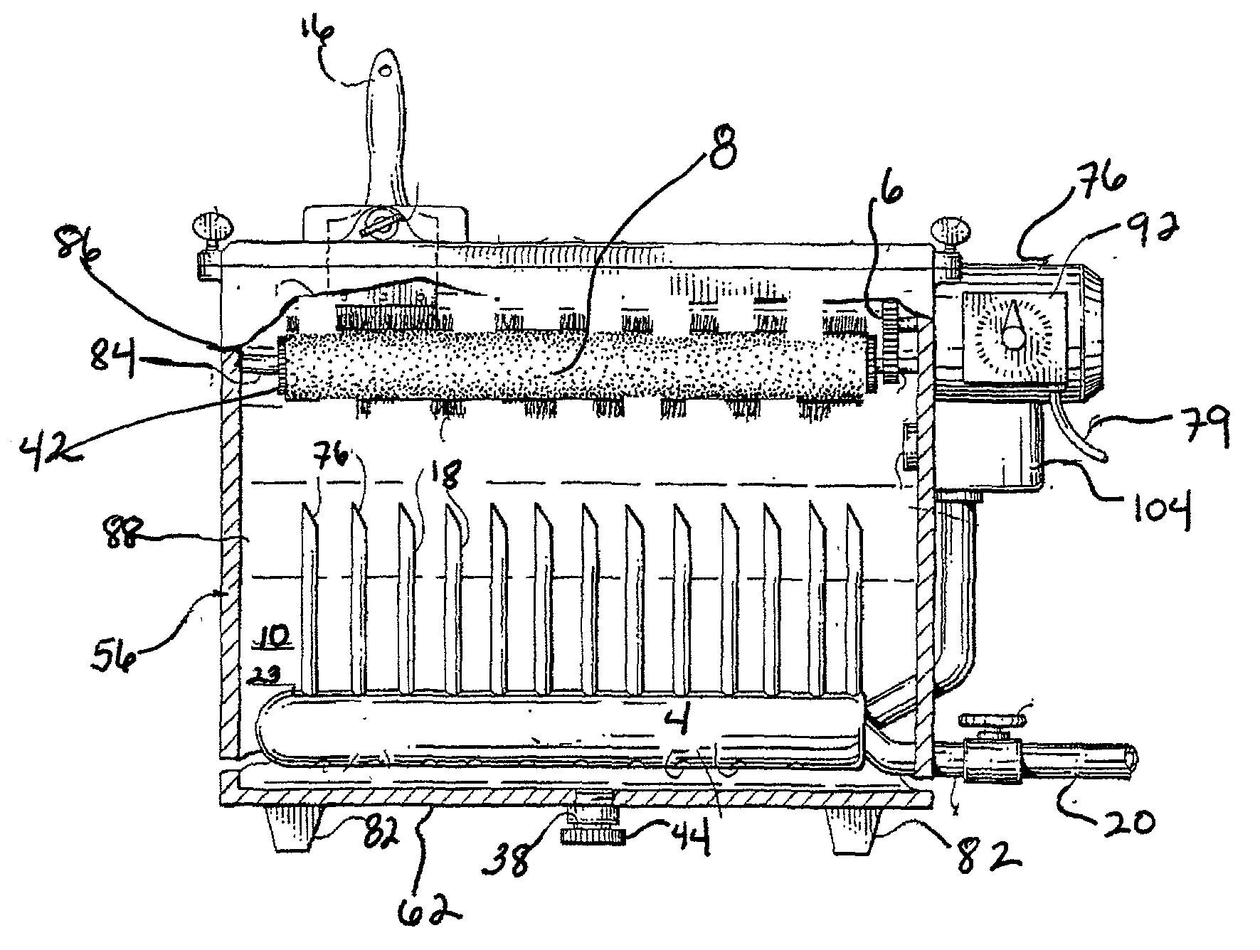
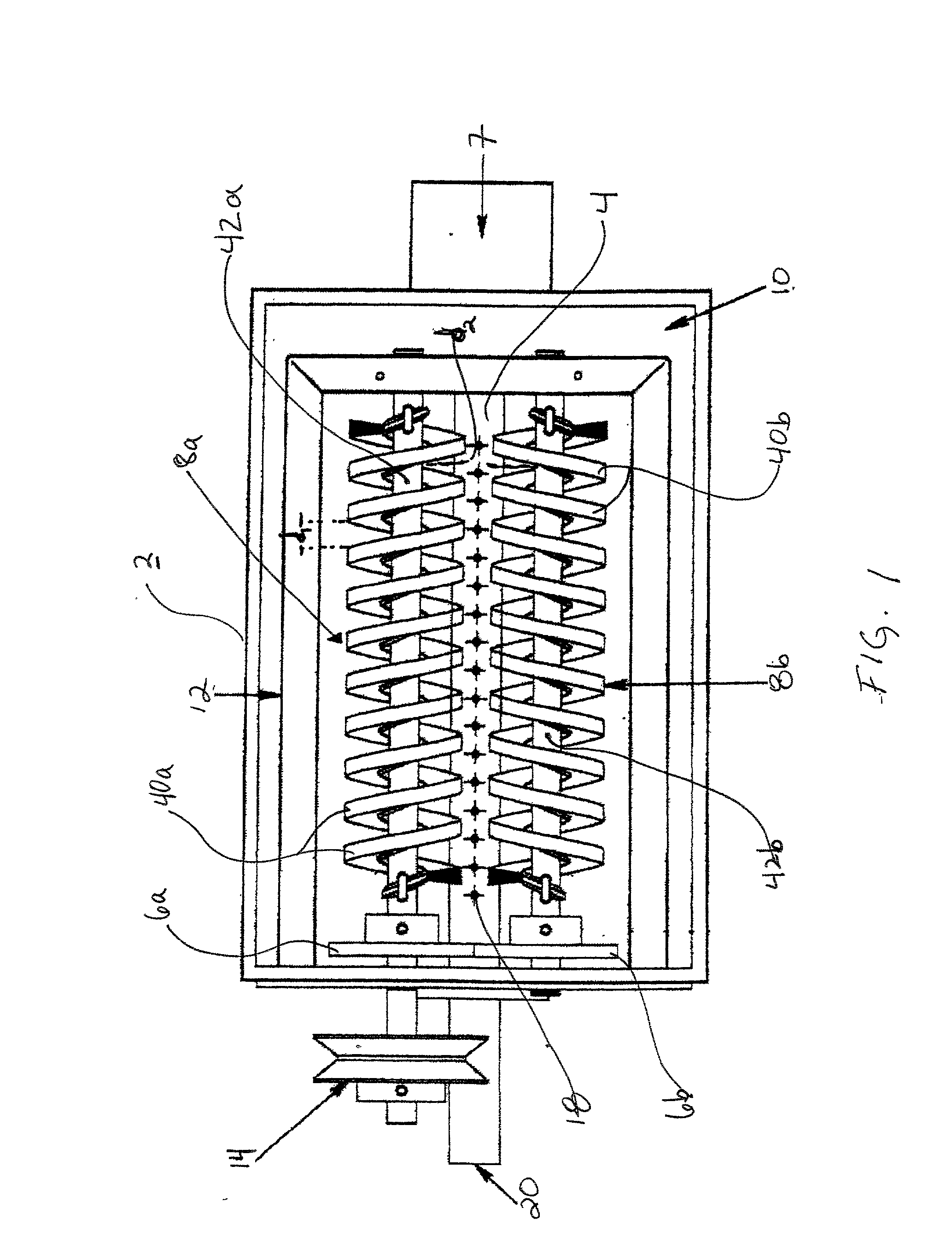
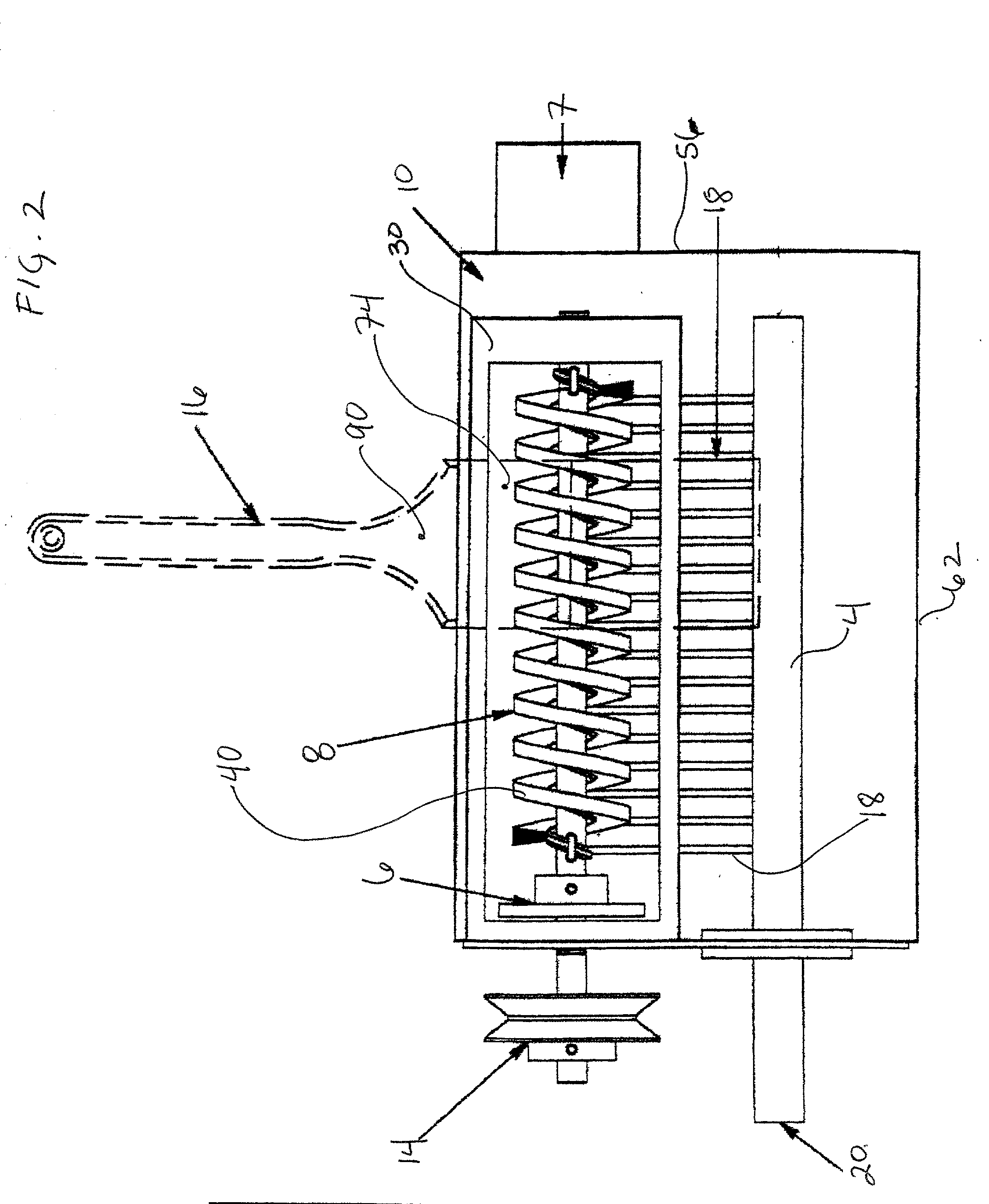
[0029] Referring generally to FIGS. 1-7 of the drawings, the device comprises a housing or container 2 having a horizontal bottom 62 and upraised sidewalls 56 defining a housing interior 11, which includes a central space 10 communicating with a top opening 72. The housing 2 is preferably comprised of a lightweight corrosion resistant material such as...


PUM


Abstract

The paintbrush-cleaning device includes a housing with an open top, a bottom drain and a means to hold paintbrushes into the housing's central space, which has paintbrush-cleaning liquid therein. A pair of rotatable radial brushes brackets the paintbrushes in the central space and are powered by an electric motor connected to the housing. A number of spaced upwardly directed jet nozzles are disposed in the central space for directing streams of cleaning liquid under pressure upwards towards the paintbrushes. An impeller pump may be connected to a manifold in the central space, from which manifold the jet nozzles extend. Two radial brushes may be used, with the members disposed opposite each other adjacent the sides of the top opening. The radial brushes bear a bristle portion comprising cleaning bristles, which is configured in a spiral along the length of the radial wound brush so that the radial brushes transport cleaning fluid upward and forward from the central space to the paintbrushes via the Archimedes screw principle. The device is simple, durable and efficient.

Description

CROSS-REFERENCES TO RELATED APPLICATIONS[0001] This patent application claims priority from U.S. Provisional Patent Application Ser. No. 60 / 245,078 filed Nov. 1, 2000 for PAINT BRUSH CLEANING DEVICE, which application is incorporated herein by this reference thereto.COPYRIGHT AUTHORIZATION[0002] A portion of the disclosure of this patent document contains material which is subject to copyright protection. The copyright owner has no objection to the facsimile reproduction by any one of the patent disclosure as it appears in the U.S. Patent and Trademark Office patent files or records, but otherwise reserves all copyright rights whatsoever.[0003] 1. Field of the Invention[0004] The present invention generally relates to cleaning means and, more particularly, to an improved paintbrush cleaning device.[0005] 2. Description of the Related Art[0006] Various types of paintbrush cleaning devices have been utilized in the past. See, for example, U.S. Pat. No. 1,542,025, which discloses a han...

Claims


Application Information

Patent Timeline
Patent Type & Authority Applications(United States)
IPC IPC(8): A46B17/06B44D3/00
CPCB44D3/006A46B17/06
Inventor BRACKETT, TED J.SMITH, C. MARTINANDERSON, MARK
Owner BRACKETT TED J
Why Eureka
Try Eureka