Portable radio communications device

a radio communication and portable technology, applied in the field of portable radio communication devices, can solve the problems of user loosening the grip of the device, incompatible with the increasing demand for smaller and smaller devices, and consuming a lot of time, and achieve the effect of convenient operation

Inactive Publication Date: 2002-05-02
TELEFON AB LM ERICSSON (PUBL)
View PDF8 Cites 30 Cited by
  • Summary
  • Abstract
  • Description
  • Claims
  • Application Information

AI Technical Summary

Benefits of technology

0013] Alternatively, when the optical emitter emits visible light, a high-tech look that could be attractive to especially young people is provided.
0014] When the circuitry for generating a control signal is further adapted to generate a selection signal for selecting an item indicated on said display by the position of said position indicator, the control means can also be used to activate e.g. a function which has been indicated by moving the position indicator to a corresponding item on the display. This is similar to the use of a mouse button on a normal computer mouse, but the selection can be performed without the addition of a...

Problems solved by technology

However this solution is relatively time consuming when the cursor has to be moved a longer distance on the display.
Further, the four keys must have a sufficiently large size and thus they occupy a considerable area on the communications device, and this is incompatible with the increasing demand for smaller and smaller devices.
This means that the user may loose the grip of the device or that the joystick itself may break off.
Also this solution takes up a considerable area on the device.
All these solutions include mechanical components which will always be subjected to some sort of mechanical wear resulting in reliability problems.
Another problem is that dirt and moisture can enter into the mechanical components and thus accelerate the wear and disturb the contact surfaces.
This problem is of particular importance with the portable communications devices, because they are often ke...

Method used


Image

  • Portable radio communications device
  • Portable radio communications device
  • Portable radio communications device

Examples


Embodiment Construction

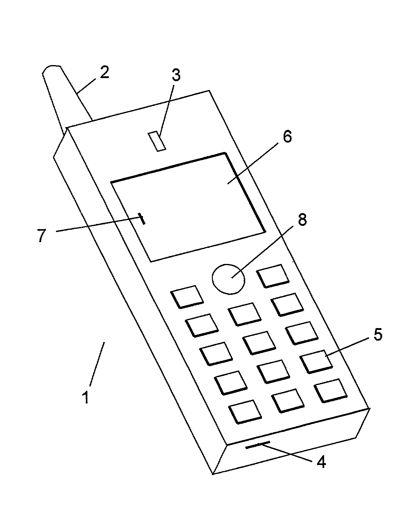
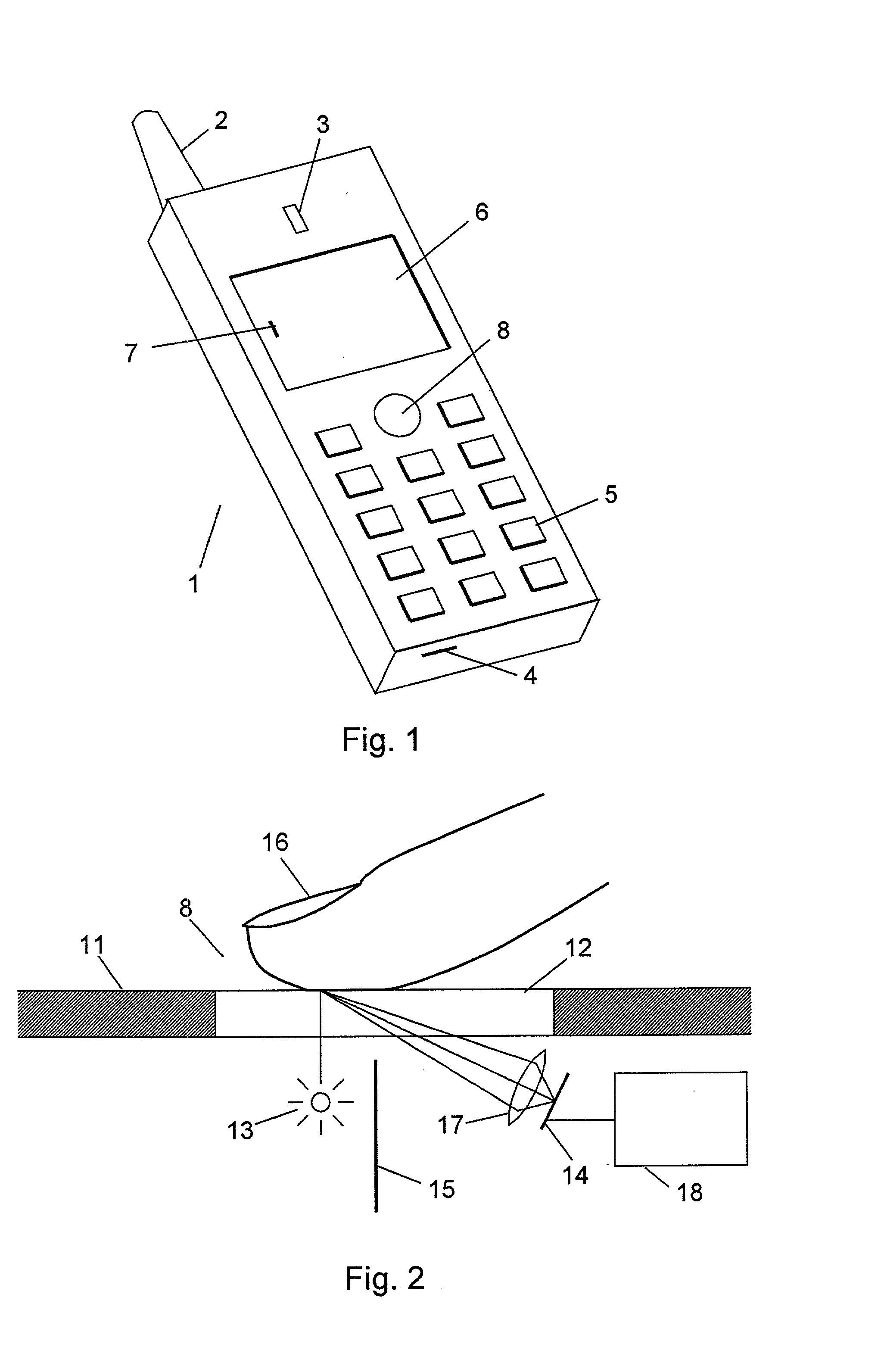
[0022] FIG. 1 shows an example of a portable radio communications device, in this case a mobile telephone 1, in which the invention can be used. The telephone has an antenna 2, a loudspeaker 3, a microphone 4 and a number of keys 5. The keys 5 are used for entering telephone numbers, messages, etc. A display 6 is provided for presentation of information to the user of the telephone. This information could be numbers or messages entered by means of the keys 5, or it could be information received by the device through the antenna 2. An example of such information could be a menu from which the user can select a specific item, which is done by moving a cursor or pointer 7 around on the display 6.

[0023] The movement of the cursor 7 is controlled by the cursor control device 8 according to the invention. This device 8 is an optical control device which will be described in more detail below. The optical control device includes a translucent window integrated into the surface of the telep...


PUM


Abstract

A portable radio communications device (1) has a display (6) on which a position indicator (7) can be positioned, and means (8) for controlling the position of the position indicator (7) on the display (6) manually by a user. The controlling means comprise an optical emitter adapted to illuminate an object through a translucent and moisture-proof surface; an optical detector adapted to detect changes in light reflected from the object due to the movement thereof; and circuitry for generating a control signal for the position of the position indicator (7) in dependence on the changes in reflected light. The optical detection of the movement of a finger provides a very easily operated control device with no need to press the finger against the device, and thus forces on the printed circuit boards are avoided. The moisture-proof surface ensures that the device is insensitive to dirt and moisture.

Description

[0001] The invention relates to a portable radio communications device having a display on which a position indicator can be positioned, and means for controlling the position of the position indicator on the display manually by a user.DESCRIPTION OF RELATED ART[0002] Modern portable radio communications devices, such as e.g. mobile telephones, are increasingly used for the presentation of information to a user on a display. This information can be e.g. call information, received messages, messages to be sent from the device or information downloaded from a network, such as the internet. In many of these situations it is necessary or convenient to be able to control the position of a position indicator, such as a pointer or cursor, on the display.[0003] Several solutions to the control of a cursor on the display of a portable communications device are known. Very common is a set of arrow keys, typically two up / down keys and two left / right keys arranged e.g. in a diamond configuratio...

Claims


Application Information

Patent Timeline
IPC IPC(8): G06F3/042G06F3/0488H04M1/247
CPCG06F3/0421G06K9/00355G06F3/04883G06V40/28
Inventor FROHLUND, STIG
Owner TELEFON AB LM ERICSSON (PUBL)
Why Eureka
Try Eureka