Anti-flashover ring for a bushing insert

a technology of anti-flashover and bushing insert, which is applied in the direction of coupling base/case, coupling device connection, transformer/inductance details, etc., can solve the problems of affecting the operation of operators, and affecting the safety of equipmen

Inactive Publication Date: 2002-05-09
JAZOWSKI ROY E +1
View PDF0 Cites 75 Cited by
  • Summary
  • Abstract
  • Description
  • Claims
  • Application Information

AI Technical Summary

Benefits of technology

[0009] In light of the foregoing, it is a first aspect of the present invention to provide a device that prevents flashover between high voltage accessory products and a mating connector as they are separated from one another.
[0010] Another aspect of the present invention is to provide an anti-flashover device that prevents a vacuum from forming between an accessory product such as a bushing insert and a mating connector as the connector is removed from the bushing insert.
[0011] Yet another aspect of the present invention is to provide an. anti-flashover device that may be retrofit onto existing bushing inserts and the like.

Problems solved by technology

One of the more dangerous tasks performed by an operator is disconnecting a live source of power by physically breaking a connection between the foregoing rather than throwing a switch.
A risk in performing such a disconnect is that the electricity from the live end of the connection may arc or flashover to ground.
Such a flashover can damage the equipment and may cause injury.
For example, one such a flashover problem has been found to occur when elbow connectors are removed from bushing inserts.
Another safety problem with bushing inserts and connectors is that the operator installing the connector on the insert does not always know when the connector is fully attached to and locked on the bushing insert.

Method used


Image

  • Anti-flashover ring for a bushing insert
  • Anti-flashover ring for a bushing insert
  • Anti-flashover ring for a bushing insert

Examples


Embodiment Construction

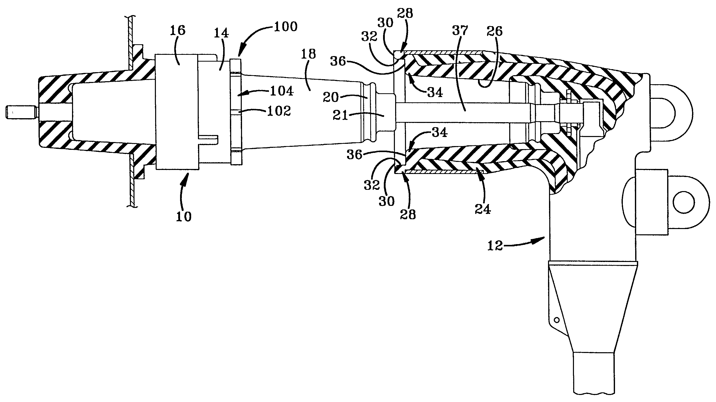
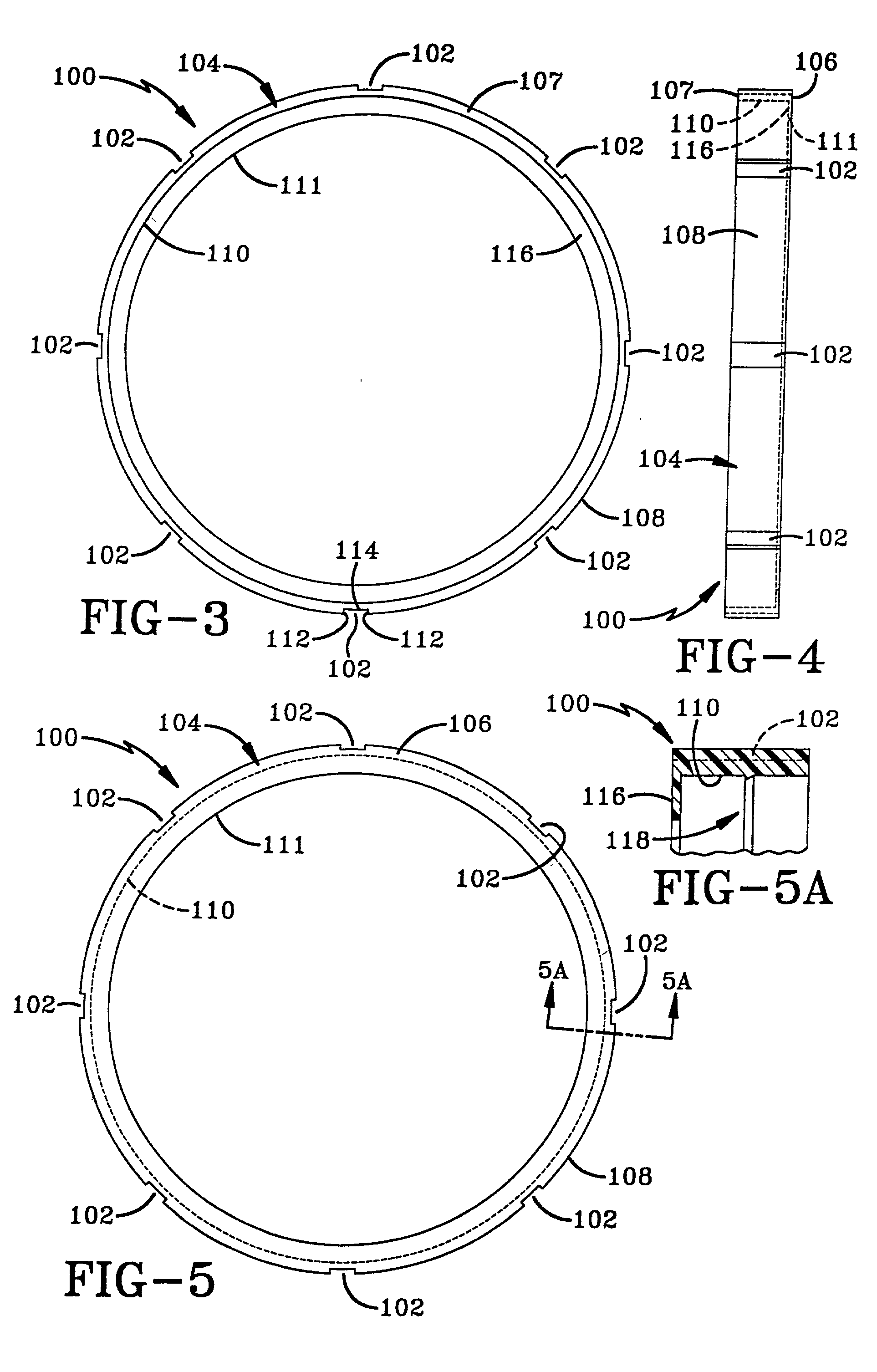
[0033] Referring now to the drawings, and more particularly FIGS. 3-10, it can be seen that an anti-flashover ring according to the present invention is designated generally by the numeral 100. Ring 100 is generally circular in shape and may be fabricated from a non-conductive material such as a thermoplastic elastomer. Whatever material is used, it is likely expandable to fit over various sized bushing inserts. Other suitable polymeric materials are also contemplated by the present invention. Ring 100 includes at least one fluid passageway or notch, each indicated generally by the numeral 102, that functions to prevent a vacuum from being formed between connector 12 and bushing insert 10 when separated from each other with ring 100 properly positioned on bushing insert 10. As used herein, fluid is defined as a liquid or gas, such as air, that tends to flow or conform to the outline of its container.

[0034] Ring 100 includes a ring-shaped body 104 that has an outer surface 108 and at...


PUM

PropertyMeasurementUnit
diameteraaaaaaaaaa
depthaaaaaaaaaa
widthaaaaaaaaaa

Abstract

The anti-flashover ring of the present invention includes a substantially cylindrical body having an outer surface with a plurality of passageways thereon. Each of the passageways pass from one of the sidewalls through the body to the other of the sidewalls of the ring. The passageways function to provide fluid communication between the atmosphere surrounding an accessory product such as a bushing insert and the interior of a connector mounted thereon when the connector is being pulled off the bushing insert. The fluid communication prevents a vacuum from forming between the connector and the bushing insert that can lead to a flashover between an electrical probe in the connector and a ground shield of the bushing insert. The anti-flashover ring is also configured to provide an indication to the operator installing the connector of when the connector is fully installed on the bushing insert. Such indication is provided by providing the ring with a width that is equal to length of the lip of the connector when the connector is fully installed. As such, the operator installing the connector continues to push on the connector until the end of the lip aligns with the end of the ring.

Description

[0001] This invention relates generally to a safety device for high voltage electrical equipment and, more particularly, to a device used on high voltage accessory products to reduce the risk of flashovers when a connector or insulated cap is removed from the accessory product. Specifically, the present invention relates to an anti-flashover ring that fits on an accessory product and prevents a flashover-promoting vacuum from forming between the accessory product and a connector as the connector is pulled off the accessory product.[0002] Safety is of paramount importance to line crew operators who deal with high voltage electrical equipment given the consequences of a mistake or an unfortunate occurrence. High voltage electrical equipment includes, but is not limited to, various sized bushing inserts, feed-through devices, multi-position junctions, and insulated or stand-off bushings. The foregoing equipment is usually held in a fixed position to receive mounting connectors such as ...

Claims


Application Information

Patent Timeline
Patent Type & Authority Applications(United States)
IPC IPC(8): H01R13/53
CPCY10S439/921H01R13/53
Inventor JAZOWSKI, ROY E.DECKER, EDWARD H.
Owner JAZOWSKI ROY E
Why Eureka
Try Eureka