Method of producing a spark plug
- Summary
- Abstract
- Description
- Claims
- Application Information
AI Technical Summary
Problems solved by technology
Method used
Image

Examples
third embodiment
[0082] The spark plug according to a third embodiment is provided substantially in the same manner as that of the first embodiment. The difference is that the earth electrodes are attached and welded after fitting the noble metal member 100 having a positioning hole 101.
[0083] FIGS. 8A to 8D are sectional side elevation views of the discharge portion of the spark plug illustrating the successive production process conditions.
[0084] At first, as shown in FIG. 8A, the noble metal member 100 having a positioning hole 101 is prepared. The end 31 of the central electrode 30 is inserted and fitted into the positioning hole 101 to support the noble metal member 100. The noble metal member 100 has the same structure as the noble metal member 80' in the second embodiment. That is, the diameter of the positioning hole 101 is determined in accordance with the diameter of the end 31 of the central electrode 30, and its outer diameter is determined in accordance with the position and size of the...
forth embodiment
[0091] The spark plug according to a fourth embodiment is provided substantially in the same manner as that of the first embodiment. The difference is that a plurality of earth electrodes 40 are formed in a unit and is attached to the one end 11 of the housing at the same time. That is, a plurality of earth electrodes 40 are connected by a connecting member 46. For this, this embodiment is applicable only to the spark plugs having a plurality of earth electrodes.
[0092] FIGS. 9A to 9D are sectional side elevation views of the discharge portion of the spark plug illustrating the successive production process conditions according to the fourth embodiment.
[0093] At first, as shown in FIG. 9A, a work including the central electrode 30 supported by the insulator 20 and the noble metal member 110 having a positioning hole 111 is prepared. The end 31 of the central electrode 30 is inserted and fitted into the positioning hole 111 to support the noble metal member 110. The noble metal member...
fifth embodiment
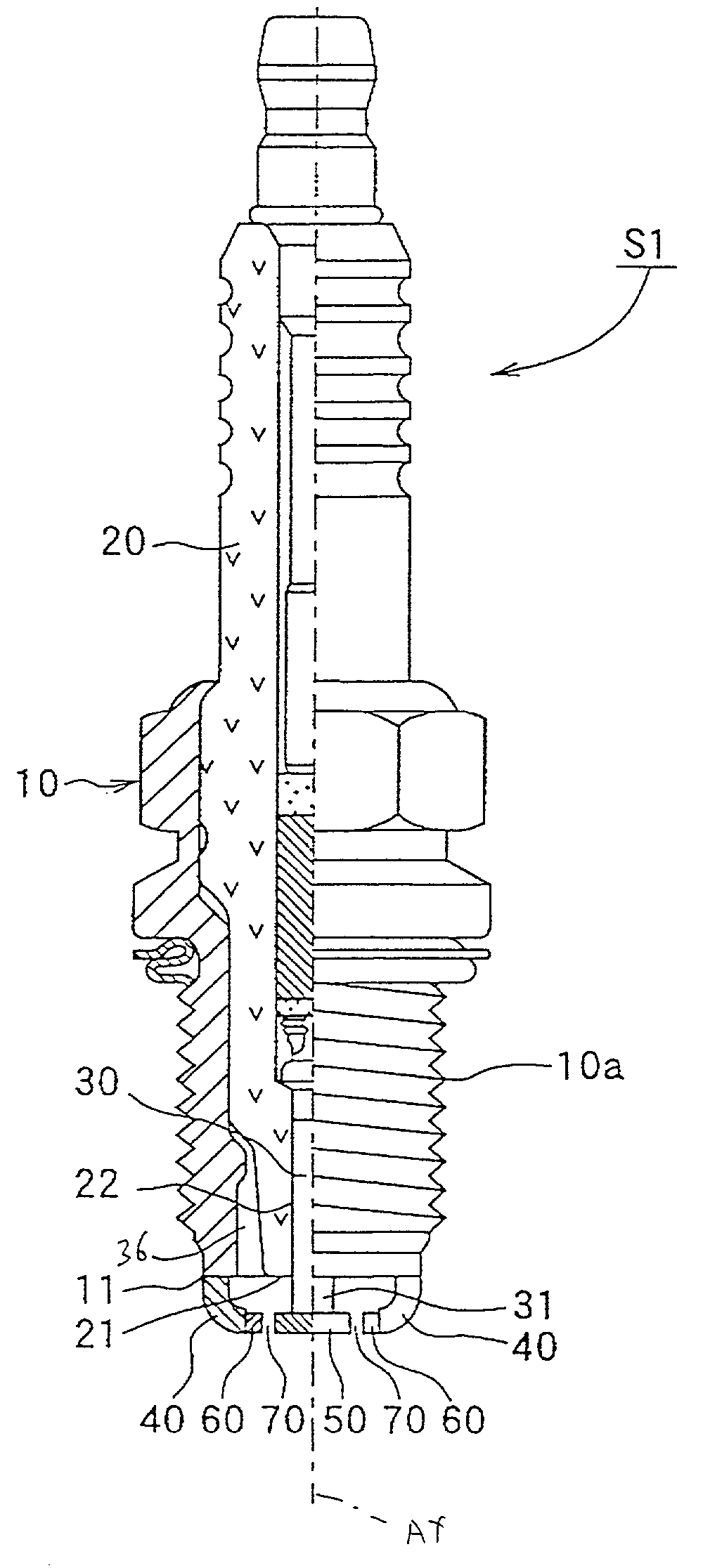
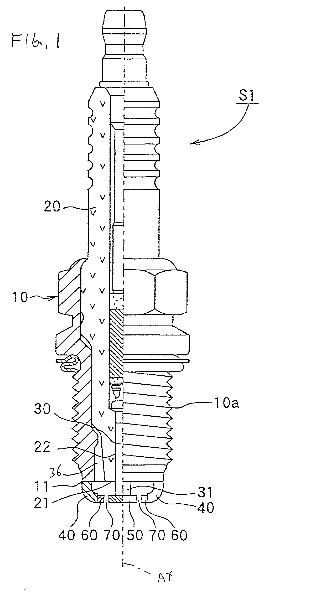
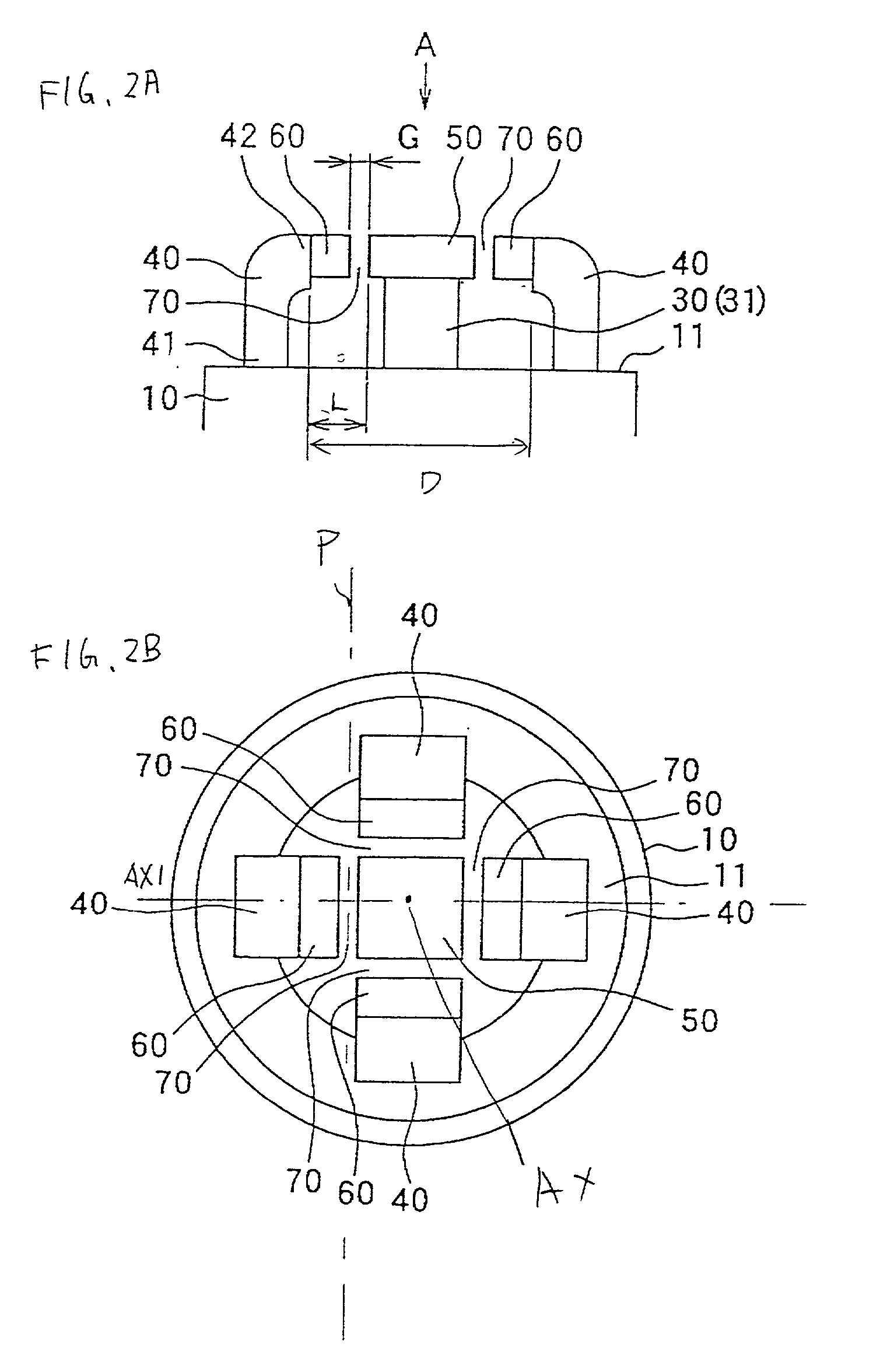
[0101] FIG. 10A is a plan view of the discharge portion of the spark plug S2 according to a fifth embodiment. FIG. 10B is a sectional side elevation view taken on the line B-B in FIG. 10A. This spark plug S2 is obtained by modifying the shape of the discharge portion of the spark plug shown in FIG. 1.
[0102] The spark plug S2 includes one central electrode 30 and earth electrodes (four earth electrodes in this embodiment) are bonded such that the earth electrodes 40 surround the central electrode 30. A central electrode chip 50 is bonded to the central electrode 30, and a ring chip 85 is bonded to respective earth electrodes 40. The inner surface of the ring chip 85 faces the central electrode chip 50 to form a spark gap 70.
[0103] The fifth embodiment provides a method of producing the spark plug S2 shown in FIGS. 10A and 10B. FIG. 10C is a perspective view of a noble metal member used for the spark plug S2.
[0104] At first, a noble metal member 120 having a circular plate shape is pr...
PUM
 Abstract
Description
Claims
Application Information