Abnormal combustion detection method for spark-ignition engine, and spark-ignition engine

a combustion detection and spark ignition technology, applied in the direction of electric control, ignition automatic control, instruments, etc., can solve the problems of high risk of preignition development, damage to the piston, and rapid rise in ignition timing

Active Publication Date: 2011-10-06
MAZDA MOTOR CORP
View PDF2 Cites 55 Cited by
  • Summary
  • Abstract
  • Description
  • Claims
  • Application Information

AI Technical Summary

Benefits of technology

[0015]In view of the above circumstances, it is an object of the present invention to provide a method capable of adequately detecting preignition which is likely to occur during o

Problems solved by technology

Specifically, once the postignition occurs, a self-ignition timing will rapidly become earlier, and a risk of developing into the preignition will become higher.
If the postignition develops into the preignition, intense noise and vibration occur, and prolonged continuation of this phenomenon is likely to cause damage to a piston, etc.
As above, the preignition is unignorable serious abnormal combustion.
Meanwhile, in cases where the ion current sensor is used to detect the preignition as in the engine disclosed in the Patent Document 1, it is likely that the preignition cannot be accurately detected in some situations.
In this case, due to impossibility to detect an ion current during a spark discharge, or influence of LC resonance noise in an electric circuit, etc., it becomes difficult to adequately detect a combustion ion current, which is likely to cause a risk of missing the preignition.
However, in th

Method used


Image

  • Abnormal combustion detection method for spark-ignition engine, and spark-ignition engine
  • Abnormal combustion detection method for spark-ignition engine, and spark-ignition engine
  • Abnormal combustion detection method for spark-ignition engine, and spark-ignition engine

Examples


Embodiment Construction

(1) Overall Structure of Engine

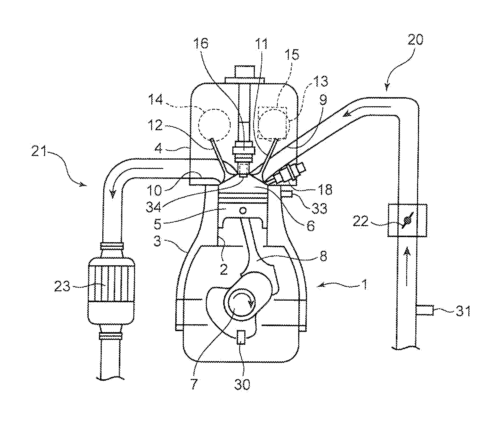
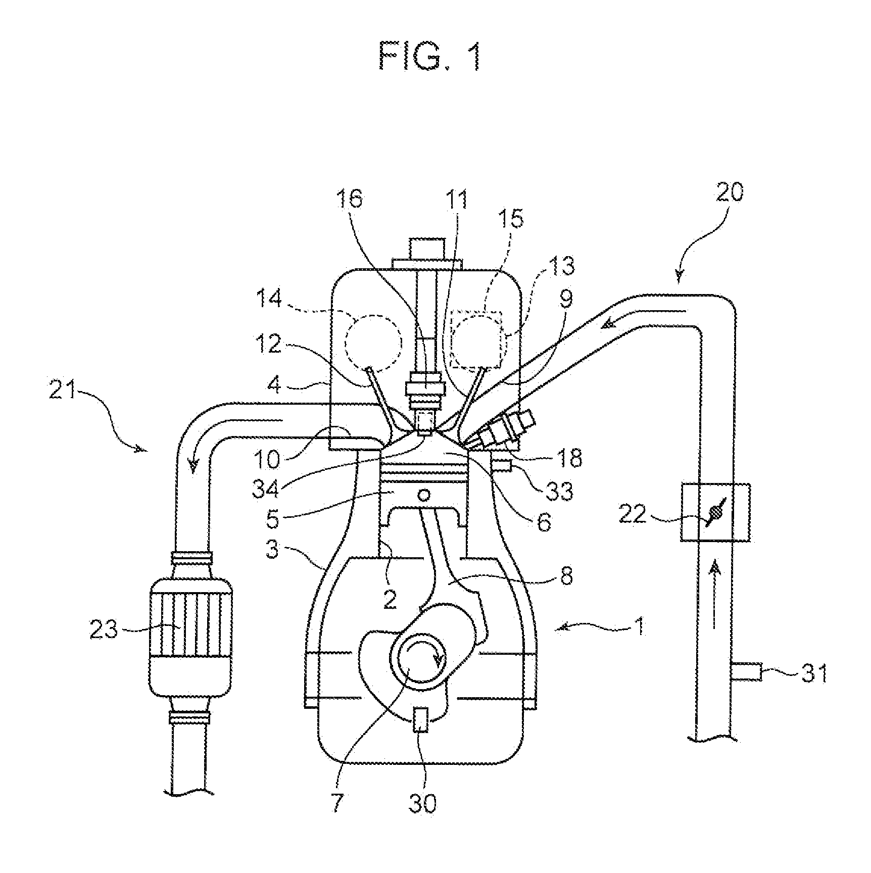
[0036]FIG. 1 is a schematic diagram showing an overall structure of a spark-ignition engine according to one embodiment of the present invention. The engine illustrated in FIG. 1 is a reciprocating piston-type multicylinder gasoline engine which is mounted in a vehicle as a power source for driving of vehicle running. An engine body 1 of the engine comprises a cylinder block 3 having a plurality of cylinders 2 arranged side-by-side in a direction perpendicular to a surface of the drawing sheet (In FIG. 1, only one of the cylinders 2 is illustrated), a cylinder head 4 provided on an upper surface of the cylinder block 3, and a plurality of pistons 5 each inserted in a perspective one of the cylinders 2 in a reciprocatingly slidable manner. Fuel to be supplied to the engine body 1 may be any type consisting mainly of gasoline. For example, the fuel may consist only of gasoline, or may comprise gasoline and ethanol (ethyl alcohol) or the like contained in...


PUM


Abstract

When a maximum value of vibration intensity (maximum vibration intensity) (Vmax) acquired from a vibration sensor (33) in a low engine speed/high engine load (operating region (R)) is equal to or greater than a given threshold value (X), a spark timing of a spark plug (16) is shifted from a point set in a normal state on a retard side with respect to a compression top dead center, farther toward the retard side. Then, when a maximum vibration intensity (Vmax2) acquired after the spark timing retard is greater than a maximum vibration intensity (Vmax1) acquired before the spark timing retard, it is determined that preignition occurs. This technique makes it possible to reliably detect preignition using the vibration sensor, while distinguishing the preignition from knocking. An in-cylinder pressure sensor for detecting an in-cylinder pressure of an engine may be used to determine the presence or absence of the preignition, in the same manner.

Description

BACKGROUND OF THE INVENTION[0001]1. Field of the Invention[0002]The present invention relates to a method for detecting abnormal combustion in a spark-ignition engine which is provided with a vibration sensor for detecting vibration of the engine, or an in-cylinder pressure sensor for detecting an in-cylinder pressure of the engine, and designed such that a spark timing of a spark plug is set on a retard side with respect to a compression top dead center (top dead center of a compression stroke), in a low engine speed / high engine load region and in a normal state where no abnormal combustion occurs. The present invention also relates to a spark-ignition engine using the method.[0003]2. Description of the Background Art[0004]Heretofore, in a spark-ignition engine equipped with a spark plug, it has been implemented to provide an ion current sensor (sensor for detecting an ion current generated by combustion of an air-fuel mixture) in a combustion chamber, and detect postignition and p...

Claims


Application Information

Patent Timeline
IPC IPC(8): G01M15/12
CPCF02D35/02F02D35/023F02D35/027F02D37/02F02D41/0002F02D41/402Y02T10/42F02P5/045F02P5/152G01L23/225Y02T10/44Y02T10/46F02D2041/001Y02T10/40
Inventor MATSUO, NAOYASHISHIME, KOUIHAYAKAWA, MOTOOMORIMOTO, HIROKIOHASHI, MIKINORI
Owner MAZDA MOTOR CORP
Why Eureka
Try Eureka