Apparatus and method for in vivo delivery of therapeutic agents

a technology therapeutic agents, applied in the field of in vivo delivery of therapeutic agents, can solve the problems of irritating the site tissue, placing electrodes, and difficulty in placing electrodes containing therapeutic agents,

Inactive Publication Date: 2002-05-09
HISAMITSU PHARM CO INC
View PDF0 Cites 10 Cited by
  • Summary
  • Abstract
  • Description
  • Claims
  • Application Information

AI Technical Summary

Problems solved by technology

However, there have been problems in placing electrodes and establishing the proper relationship between the position of the electrodes.
In addition, multiple administrations have required multiple applications of electrodes and therapeutic agents, entailing repeated affixing and removing of electrodes, thereby irritating the site tissue.
In constructing an actual device, difficulties have arisen in containing the therapeutic agents on the surface of the electrodes and in placing the surface containing therapeutic agents and the surface of the electrodes in direct contact with the skin.
Thus, conventional devices which use electroporation have unresolved problems.
While there are examples of in vitro experiments using electroporation and iontophoresis jointly, conventional techniques have not been able to create a device which can practically jointly use both types of electrodes.

Method used


Image

  • Apparatus and method for in vivo delivery of therapeutic agents
  • Apparatus and method for in vivo delivery of therapeutic agents
  • Apparatus and method for in vivo delivery of therapeutic agents

Examples


first embodiment

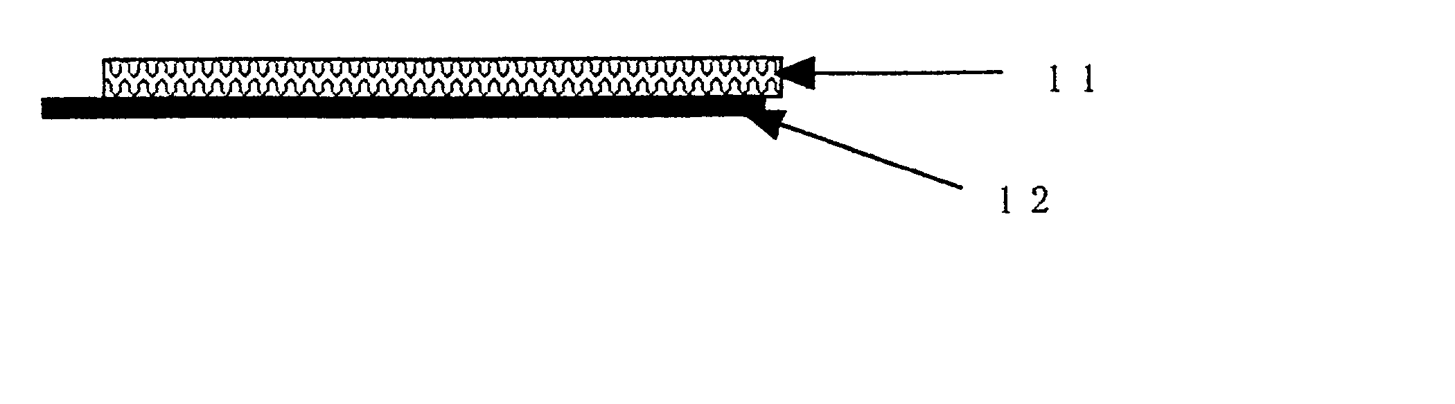
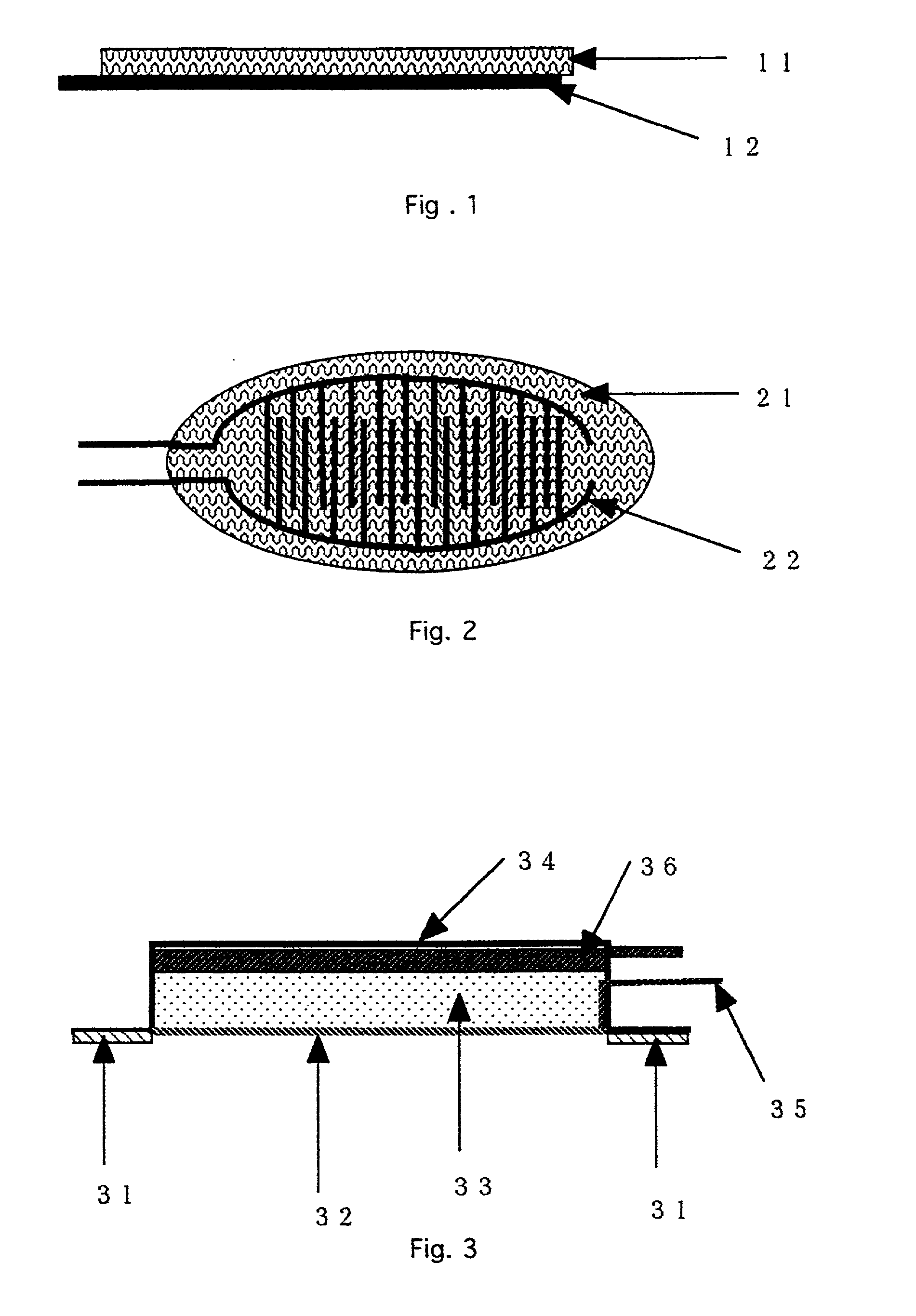
[0026] The structure and operational parameters of preferred embodiments of the invention will be explained below making references to the Drawings. FIG. 1 and 2 show a device according to one embodiment of the invention. FIG. 1 is a side view of the device. FIG. 2 is a planar view of the same device shown in FIG. 1. An agent permeable membrane 11, 21 (in FIG. 1 and 2, respectively) is preferably a porous membrane. A contact electrode pair for electroporation 12, 22 is affixed to the agent permeable membrane 11, 21, such that the device of the first embodiment forms an electrode membrane. The contact electrode pair 12, 22 is shown with two comb-like electrodes in an interdigitated pattern (though the electrodes do not contact one another), but the invention is not limited to that form. A portion of the contact electrode pair 12, 22 is shown as protruding from the membrane 11, 21. However, the contact electrode pair 12, 22 can also be entirely embedded in the agent permeable membrane...

second embodiment

[0032] the invention, as shown in FIG. 4, is a device for electroporation integrating the above-described electrode membrane. An adhesion layer 41 includes an adhesive for keeping the device in contact with skin or mucosa. An electrode membrane for electroporation 42, as described above and shown in FIG. 1 and 2, is on a lower portion of the device. A pharmaceutical composition layer 43 contains a therapeutic agent to be administered. A casing 44 forms a reservoir which contains the pharmaceutical composition layer 43. A contact electrode terminal 45 for connecting a contact electrode pair (within the electrode membrane 42; see the contact electrode pair 12, 22 in FIG. 1 and 2) to a power supply device (not shown) protrudes from the casing 44.

[0033] In use, a device according to the second embodiment is applied to a site of administration, held in place by the adhesive. The reservoir may already contain the pharmaceutical composition or the pharmaceutical composition may be added af...


PUM


Abstract

Electroporation electrodes are laminated to a permeable membrane to form an electrode membrane. Such an electrode membrane is useful for a continuous controlled delivery of a therapeutic agent through the skin or mucosa, when placed in direct contact with the skin or mucosa and by application of electric field pulses at specified intervals. An electrode membrane can be assembled such that it incorporates an iontophoretic electrode in the same device. This device can be jointly utilized for electroporation and iontophoretic drug delivery through the skin and mucosal membrane.

Description

[0001] This is a continuation-in-part of U.S. application Ser. No. 08 / 964,872, filed Nov. 5, 1997 (pending).[0002] The invention relates to delivery of therapeutic agents, and more particularly to a method and apparatus for in vivo delivery of therapeutic agents through the skin or mucosa using an electromotive force such as electroporation or iontophoresis. BACKGROUND INFORMATION[0003] Electroporation, which includes electropermealization, involves the creation of aqueous pathways in lipid bilayer membranes by the application of a brief electric field pulse. Electroporation has found wide-spread application in molecular biology and in transgenics as a method of introducing DNA or other material to a cell by momentarily charging the cell with a high voltage. In recent years, this technique has also been applied to the delivery of therapeutic agents through skin or mucosa. A pore or opening is created in the skin or mucosa by an electric field created by the positive and negative dif...

Claims


Application Information

Patent Timeline
Patent Type & Authority Applications(United States)
IPC IPC(8): A61N1/30A61N1/32
CPCA61N1/042A61N1/0424A61N1/327A61N1/0444A61N1/044
Inventor MORI, KENJINOZAWA, IWAOSATO, SHUJI
Owner HISAMITSU PHARM CO INC
Why Eureka
Try Eureka