Liquid crystal display apparatus

a display apparatus and liquid crystal technology, applied in the field of display apparatus, can solve the problems of reducing the luminance of fluorescent lamps themselves, difficult for display apparatuses to implement the complete motion-frame picture display, and difficult to achieve the effect of displaying an image comparable to that of conventional crts

Inactive Publication Date: 2002-05-16
HITACHI DISPLAYS +1
View PDF15 Cites 297 Cited by
  • Summary
  • Abstract
  • Description
  • Claims
  • Application Information

AI Technical Summary

Problems solved by technology

Being not limited to the liquid crystal display apparatus, however, in the display apparatuses referred to as the flat panel displays, the implementation of a higher luminance for displaying an image comparable to that of the conventional CRT has also become an important problem.
On account of this, it has been regarded as difficult for the display apparatus to implement the complete motion-frame picture display.
Meanwhile, if there exist surplus mercury atoms inside the fluorescent lamps, the surplus mercury atoms heighten a probability that ultraviolet rays generated inside the fluorescent lamps by the collision between the mercury atoms and the electrons are absorbed into the mercury atoms, eventually decreasing the luminances of the fluorescent lamps themselves.
This eventually decreases the luminance efficiency of the directly-under type light-source unit as a whole.
Also, if the electric powers applied to the respective fluorescent lamps are increased in order to heighten the luminance of a displayed image, the resultant fever by the fluorescent lamps locally heats the liquid crystal cells, thereby reducing the uniformity as well.
This condition makes it difficult to raise, up to 300 cd / m.sup.2 or higher, the display luminance by a transverse electric-field type liquid crystal display apparatus.
Also, when the above-described technology of adjusting the luminance of the light-source for each image included in the motion-frame picture signal is executed toward the liquid crystal display apparatus, from a practical standpoint, it is difficult to set the timing with which the lamp current, which is fed to the light-source at the time of displaying the image that is bright as a whole, is lowered from the value higher than the above-described reference current down to the reference current.
However, the timing with which the lamp current is switched in this manner cannot help being set empirically in accordance with, for example, the correlation between measurement data of the temperature increase in the light-source (i.e., the fluorescent lamps) and the luminance of the light-source.
Also, if the usage conditions for the display apparatus the examples of which include even a difference in the room temperature or the like should be taken into consideration, it is extremely difficult to set the timing with which the lamp current is switched.
This, in other words, means the following: Even if this technology is applied to the liquid crystal display apparatus, when displaying an image the brightness of which remains almost unchanged over a certain fixed time-period (i.e., a time-period during which display data of a plurality of frames is transferred to the liquid crystal display apparatus), it is difficult to enhance the contrast ratio thereof.

Method used


Image

  • Liquid crystal display apparatus
  • Liquid crystal display apparatus
  • Liquid crystal display apparatus

Examples


Embodiment Construction

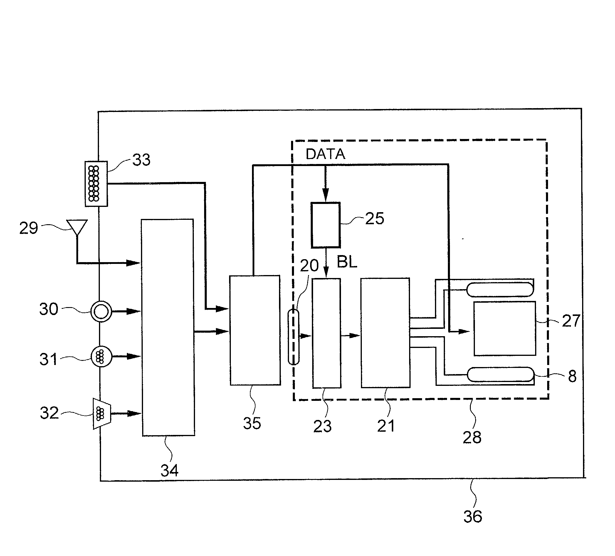
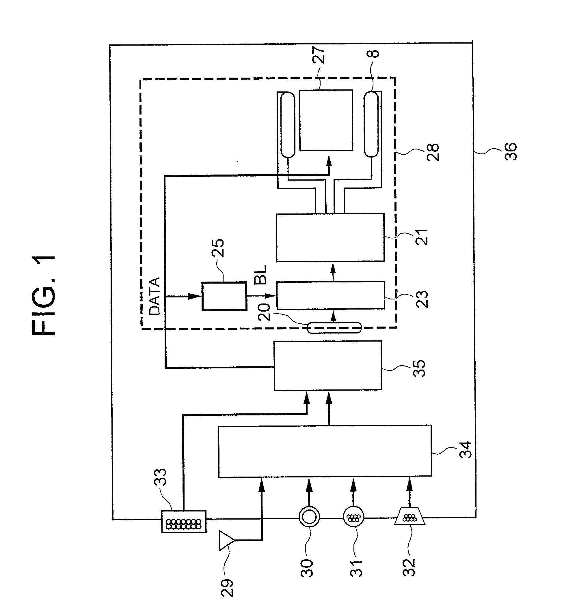
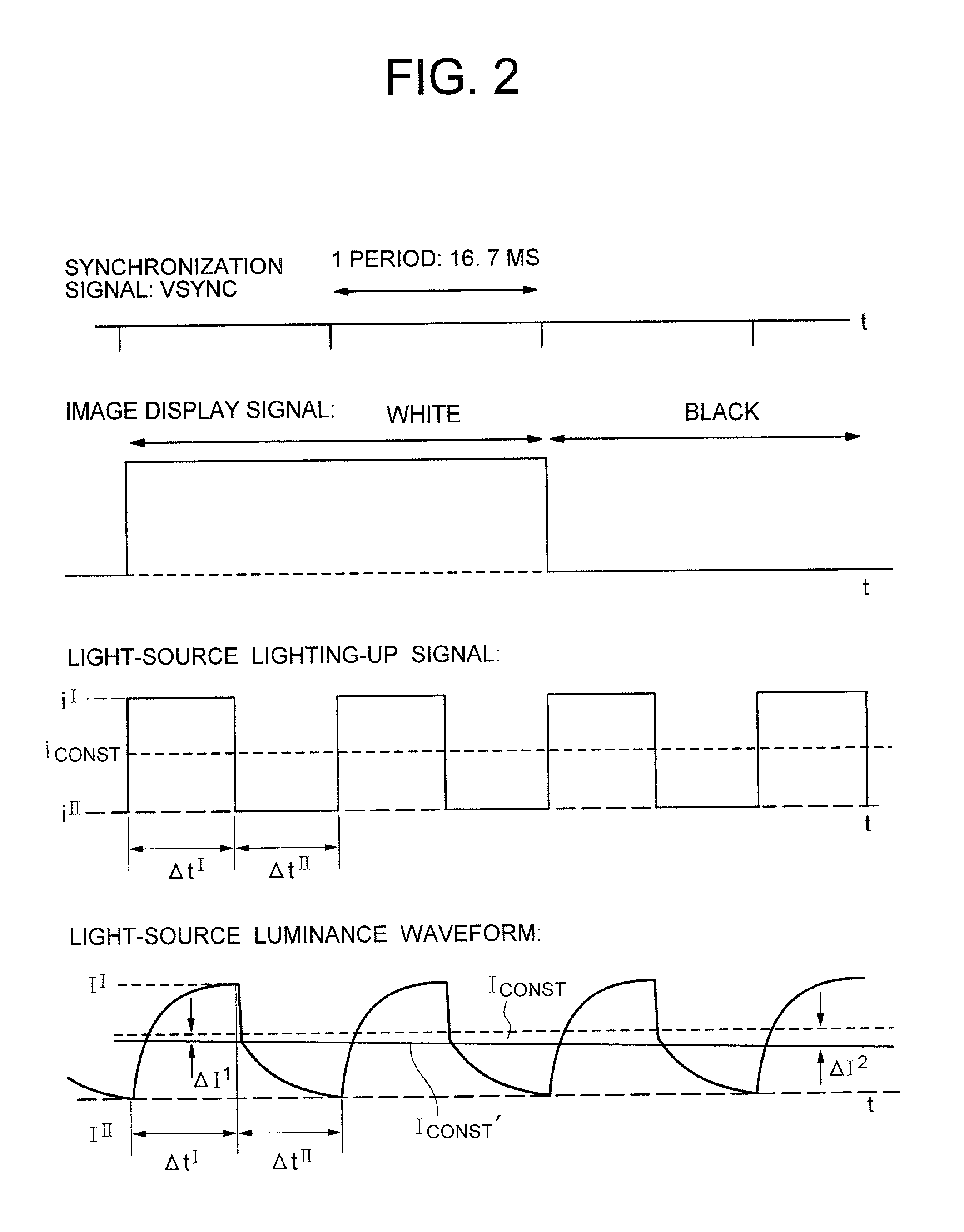
[0028] The present invention includes a panel on which a plurality of pixels are located, a light-source for visualizing an image displayed on the plurality of pixels, and a controlling circuit for controlling the light-source. Here, during a 1st time-period, the controlling circuit feeds the light-source an electric current having a 1st intensity. During a 2nd time-period, the controlling circuit feeds the light-source an electric current having a 2nd intensity (which differs from the 1st intensity). Also, the controlling circuit repeats the 1st time-period and the 2nd time-period periodically. Furthermore, the controlling circuit controls the light-source so that the intensity of a light emitted from the light-source in this period (i.e., an integrated value obtained by integrating the luminance of the light during this period) will become higher than an integrated value of the luminance in the case where the light-source is lit up by a rating electric current during the same time...


PUM

PropertyMeasurementUnit
display luminanceaaaaaaaaaa
thicknessaaaaaaaaaa
electric currentaaaaaaaaaa

Abstract

The present invention includes a panel on which a plurality of pixels are located, a light-source for visualizing an image displayed on the plurality of pixels, a controlling circuit for controlling the light-source, and an image-signal tone characteristic controlling circuit. Moreover, the light-source controlling circuit has a function of repeating a period. Here, the period includes a 1st time-period during which an electric current having a 1st intensity is fed to the light-source, and a 2nd time-period during which an electric current having a 2nd intensity differing from the 1st intensity is fed to the light-source. The light-source controlling circuit controls the 1st time-period and the 2nd time-period in accordance with display information. Also, in accordance with the display information as well, the tone characteristic controlling circuit is controlled so that the excellent contrast will be always available.

Description

[0001] 1. Field of the Invention[0002] The present invention relates to a display apparatus using a liquid crystal display device, an electroluminescence device, or the like. More particularly, it relates to a display apparatus having a light-source that is suitable for enhancing the luminance of the display screen with a high-efficiency and for making the luminance uniform on the display screen.[0003] 2. Description of the Related Art[0004] The display apparatus, which uses the liquid crystal display device (which is also referred to as "liquid crystal display panel"), the electrolumines-cence device (which, depending on a fluorescent material used, is classified into an organic-family and an inorganic-family and, hereinafter, is referred to as "EL device"), a field emission device (which, hereinafter, is referred to as "FE device"), or the like, performs the image display. However, unlike the case of a Braun tube (which, hereinafter, is referred to as "CRT", i.e., "cathode ray tub...

Claims


Application Information

Patent Timeline
Patent Type & Authority Applications(United States)
IPC IPC(8): G02F1/133G02F1/1335G02F1/13357G09F9/00G09G3/20G09G3/34G09G3/36
CPCG02F1/133604G09G2360/16G09G3/2011G09G3/2018G09G3/2077G09G3/342G09G3/3648G09G2310/024G09G2310/08G09G2320/0252G09G2320/0257G09G2320/0261G09G2320/062G09G2320/0633G09G2320/064G09G2320/0673G09G2320/103G09G2340/16G02F2001/133612G02F1/133612G02F1/133
Inventor NITTA, HIROYUKIMAEDA, TAKESHIKAWABE, KAZUYOSHIHIRAKATA, JUNICHI
Owner HITACHI DISPLAYS
Why Eureka
Try Eureka