Centralized bicarbonate mixing system

a bicarbonate and mixing system technology, applied in the direction of dissolving systems, transportation and packaging, dissolving, etc., can solve the problems of many on-the-job injuries, physical difficulty in lifting large bags of bulk materials, and medical complications of patients using the mixtur

Inactive Publication Date: 2002-05-16
THE COMFORT GROUP INC
View PDF17 Cites 27 Cited by
  • Summary
  • Abstract
  • Description
  • Claims
  • Application Information

AI Technical Summary

Benefits of technology

[0011] The present invention is developed to reduce the opportunity for having an open tank while preparing dialysate and to make the mixing process more ergonomic and faster. This is accomplished by reducing the height of the port for charging the solid bicarbonate powder, using a funnel and ejector to wet and mix the powder with circulating permeate and agitating the mix tank with nozzles driven by the re-circulating flow of fluid.
[0013] Still another object of the present invention is the provision of an additive mixing system which is completely closed so as to prevent contamination of the solution.
[0014] Yet another object of the present invention is to provide a system for mixing water and additives which does not require bags of additive powder to be lifted overhead into large mixing tanks.
[0015] Still another object of the present invention is the provision of systems for mixing water and additives which are economical.

Problems solved by technology

There are several problems with such systems.
First, the mixing tank is typically an open top tank which allows the mixture to be contaminated which leads to medical complications for the patients using the mixture.
Second, it is physically difficult to lift the large bags of bulk material into the open top tank, and the operation of this equipment leads to many on-the-job injuries, such as back strains and the like.
The primary difficulty with the Jonsson, et al. system is its high cost.

Method used


Image

  • Centralized bicarbonate mixing system
  • Centralized bicarbonate mixing system
  • Centralized bicarbonate mixing system

Examples


Embodiment Construction

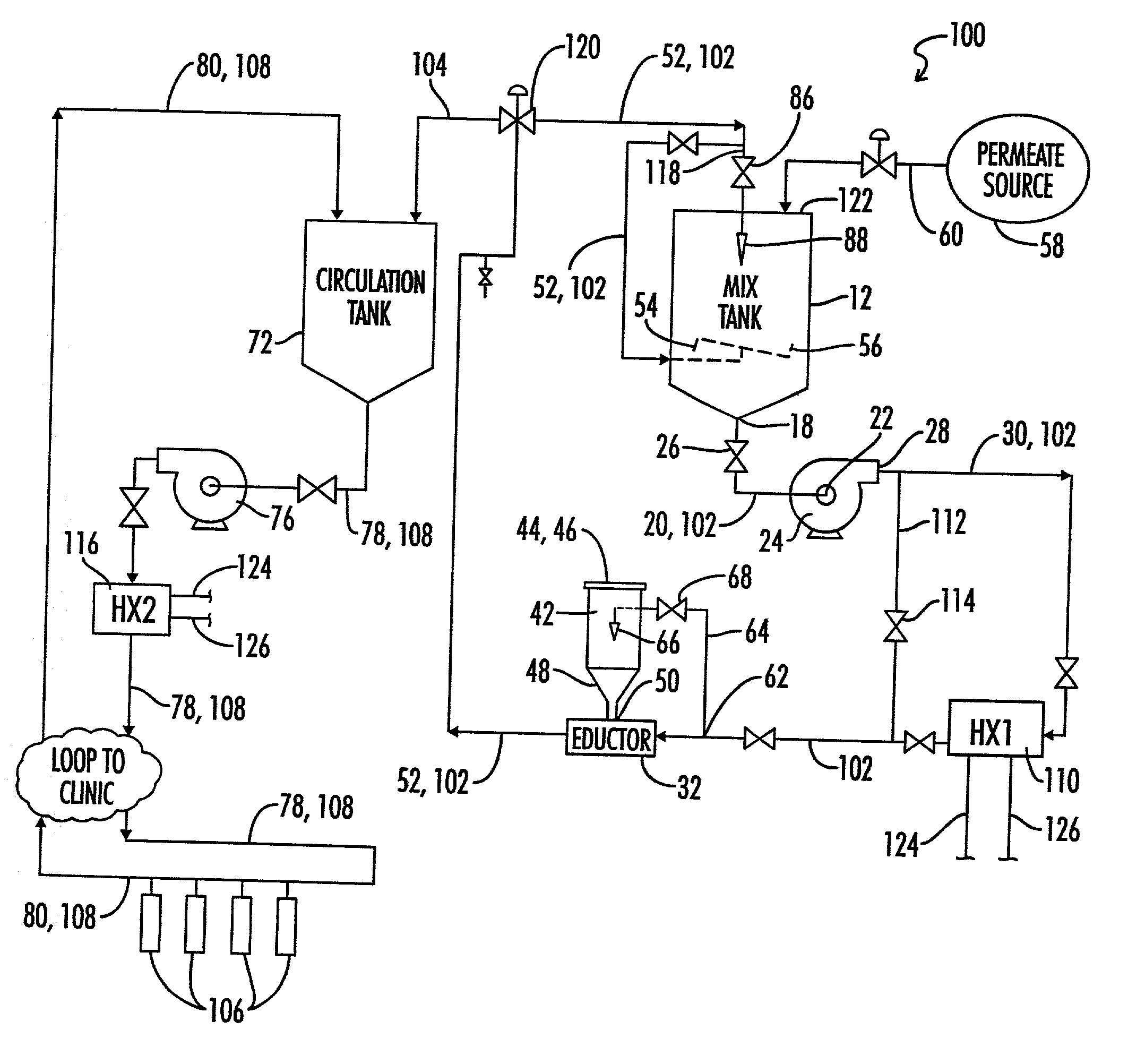
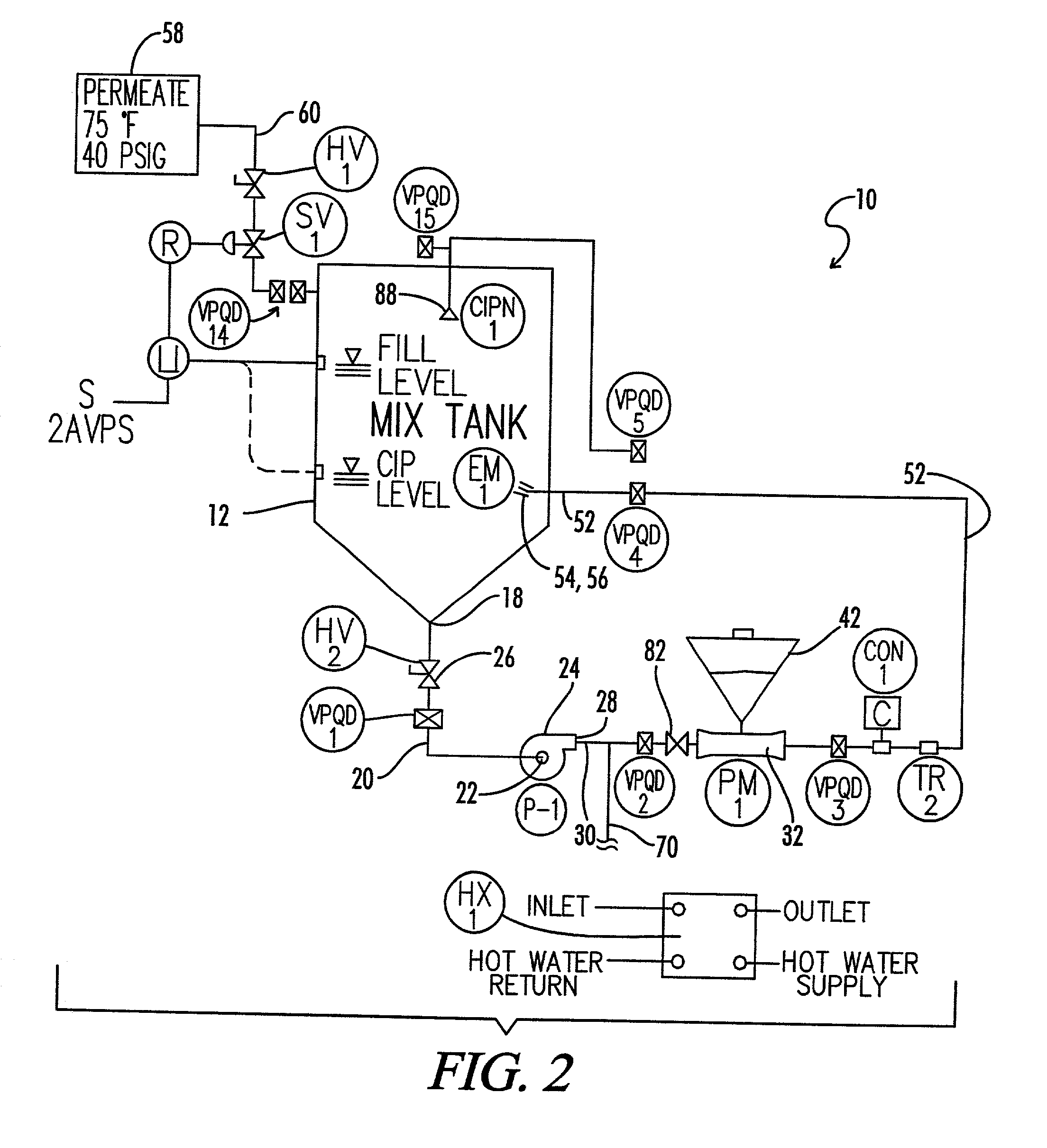
of Operation and Heat Disinfection of Mix Tank System of FIG. 2

[0044] To fill the mix tank 12 the following steps are conducted:

[0045] 1. The mounting position for the capacitance switch cut off is selected for the desired volume of solution in the tank;

[0046] 2. The valve designated HV2 is closed;

[0047] 3. The valve HV1 is opened;

[0048] 4. The "on" switch is depressed thus opening the normally closed solenoid valve designated SV1;

[0049] 5. The tank 12 is allowed to fill.

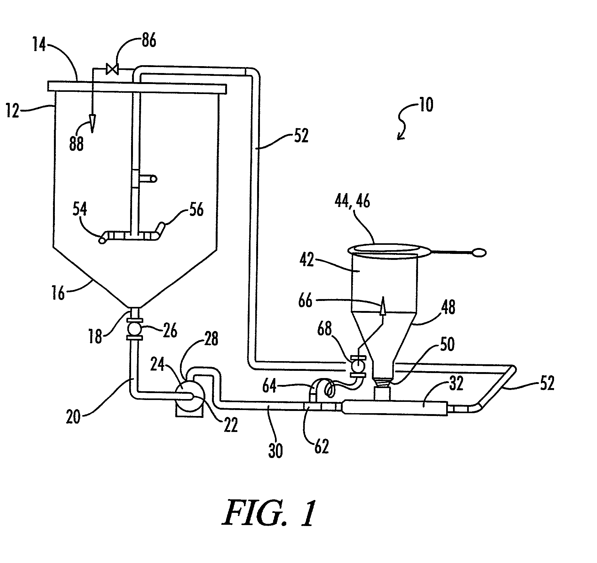
[0050] The operation of mixing the dry bicarbonate powder from hopper 42 LOW includes generally the following steps:

[0051] 1. The desired amount of pre-mixed NAHCO3 is added to hopper 42 as required by the volume of solution to be mixed and the formula to be used;

[0052] 2. The top of the hopper 42 is closed with lid 46;

[0053] 3. Valve HV2 is opened and the circulation pump 24 is turned on. Note that the discharge line 52 must be connected to the tank 12 through the valve ported quick disconnect designated as VPQD4;

[...


PUM

PropertyMeasurementUnit
temperatureaaaaaaaaaa
suction inletaaaaaaaaaa
heataaaaaaaaaa

Abstract

A centralized bicarbonate mixing system is provided for a plurality of dialysis machines of a dialysis clinic. The system includes a source of purified water, a mix tank, an eductor having a hopper for receiving dry bicarbonate material, a mixing pump and a mixing conduit loop connecting the mixing pump, the eductor and the mix tank so that as water is circulated by the mixing pump through the mixing conduit loop, the dry bicarbonate material is drawn into the eductor and mixed with the water. The system further includes a circulation tank, and a transfer conduit connecting the mixing conduit loop to the circulation tank, so that a mixed bicarbonate solution can be transferred from the mixing conduit loop to the circulation tank. The system further includes a circulation pump, and a circulation supply conduit connecting the circulation tank and the circulation pump so that mixed bicarbonate solution can be pumped from the circulation tank to the dialysis machines. The system is preferably constructed of cross-linked polyethylene and / or polypropylene plastic pipe and fittings, and is provided with heat exchangers so that the same can be heat disinfected. Furthermore, the use of the eductor and closed hopper allows for easy loading of dry bicarbonate material into the system, and for sanitary mixing of a batch of bicarbonate solution in the closed system.

Description

[0001] This application claims benefit of our co-pending Provisional U.S. Patent Application Serial No. 60 / 137,647 filed Jun. 4, 1999.[0002] 1. Field of the Invention[0003] The present invention relates generally to apparatus for mixing additives and water for medical purposes, and more particularly, but not by way of limitation, to apparatus for mixing a bicarbonate solution for use with dialysis machines.[0004] 2. Description of the Prior Art[0005] Conventional prior art centralized mixing systems have used a mixing tank into which water was directed and into which bulk quantities of powered additives have been dumped into the open top of the tank. The water and dry additives are then mixed through the use of a mechanical mixer. The mixed solution is then pumped to a storage tank from which it is delivered to the individual dialysis machines.[0006] There are several problems with such systems. First, the mixing tank is typically an open top tank which allows the mixture to be cont...

Claims


Application Information

Patent Timeline
Patent Type & Authority Applications(United States)
IPC IPC(8): A61M1/16B01F3/12
CPCA61M1/1656A61M1/1686B01F5/106B01F1/0038B01F5/0413B01F1/0022A61M1/1662A61M1/1666A61M1/1668B01F21/30B01F21/20B01F25/312B01F25/53A61M1/1657
Inventor RUSSELL, RICHARD M.PETERSON, MICHAEL J.
Owner THE COMFORT GROUP INC
Why Eureka
Try Eureka