Dynamic damper and dynamic damper-installed tennis racket

a tennis racket and dynamic damper technology, which is applied in the field of dynamic damper and dynamic damper installed tennis rackets, can solve the problems of generating more unpleasant vibration, consuming energy, and reducing and damping the vibration and shock of the racket frame quickly,

Inactive Publication Date: 2002-05-16
DUNLOP SPORTS CO LTD
View PDF0 Cites 33 Cited by
  • Summary
  • Abstract
  • Description
  • Claims
  • Application Information

AI Technical Summary

Benefits of technology

[0011] It is a second object of the present invention to provide a dynamic damper-installed tennis racket reducing vibrations of the racket frame in the in-plane direction in addition to the out-of-plane direction and having a vibration damping factor of not less than 1% in the in-plane direction and in the out-of-plane direction to reduce burden on a player's arm and allow a player to have a favorable feeling when the player hits a ball with the tennis racket.

Problems solved by technology

The dynamic damper vibrates at the same frequency as that of the racket frame, thus consuming energy and reducing and damping the vibration and shock of the racket frame rapidly.
When the player hits a ball with at a position apart from the axis of the racket frame, the player feels a shock generated by the rotation of the grip very unpleasant.
It is said that a so-called large racket having a large face area (area of gut-stretched part) developed to fly the ball a long distance generates more unpleasant vibration than a tennis racket having a small face area.
This is because the large racket is liable to flex in the in-plane direction owing to the large face area.
Thus it is difficult for a player to swing the tennis racket and for the entire dynamic damper to vibrate in the in-plane direction in particular.
Consequently the vibration of the dynamic damper is bad, which causes the dynamic damper to have a low effect of damping the vibration of the racket frame.
If the thickness of the viscoelastic part is set to less than 2.5 mm, it is difficult for the viscoelastic part to vibrate.
On the other hand, if the thickness of the viscoelastic part is set to more than 5.5 mm, the viscoelastic part may be an interference when the dynamic damper is installed on the racket frame or the dynamic damper looks unattractive.
The total weight of the dynamic damper is set to not less than 8 g nor more than 23 g. If the total weight of the dynamic damper is set to less than 8 g, the dynamic damper has an insufficient vibration reduction performance.
On the other hand, if the total weight of the dynamic damper is set to more than 23 g, the racket frame has poor handling performance.
Thus the dynamic damper is incapable of generating the dynamic motion and the resonant phenomenon sufficiently.
Thus the dynamic damper is incapable sufficiently displaying an action of relieving and reducing shocks and vibrations.
If the thickness of the entire dynamic damper is less than 3.0 mm, it is difficult for the dynamic damper to vibrate.
If the thickness of the entire dynamic damper is more than 7.0 mm, the dynamic damper may be an interference when the dynamic damper is installed on the racket frame or the dynamic damper looks unattractive.
If the specific gravity thereof is more than 25, metal which can be used is rare and expensive or difficult to obtain.
Gold, silver, and the like are expensive.
If the particle diameter is less than 1 .mu.m, the metal powder is liable to fly or flocculate.
Thus the metal powder is difficult to disperse in the highmolecular compound when they are mixed.
If the particle diameter is more than 250 .mu.m, i.e., if the metal powder is large, it is difficult to make the mass-adding part thin.
The dynamic damper vibrates earlier than the racket frame, thus consuming vibration energy of the racket frame and damping the vibration of the racket frame rapidly.

Method used


Image

  • Dynamic damper and dynamic damper-installed tennis racket
  • Dynamic damper and dynamic damper-installed tennis racket
  • Dynamic damper and dynamic damper-installed tennis racket

Examples


example 2

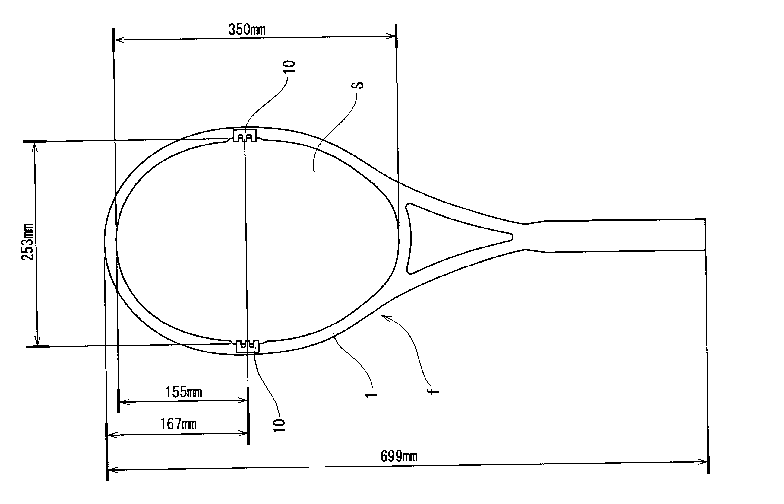
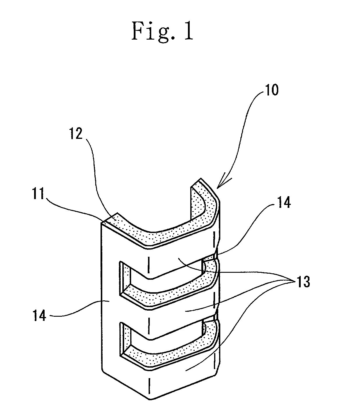
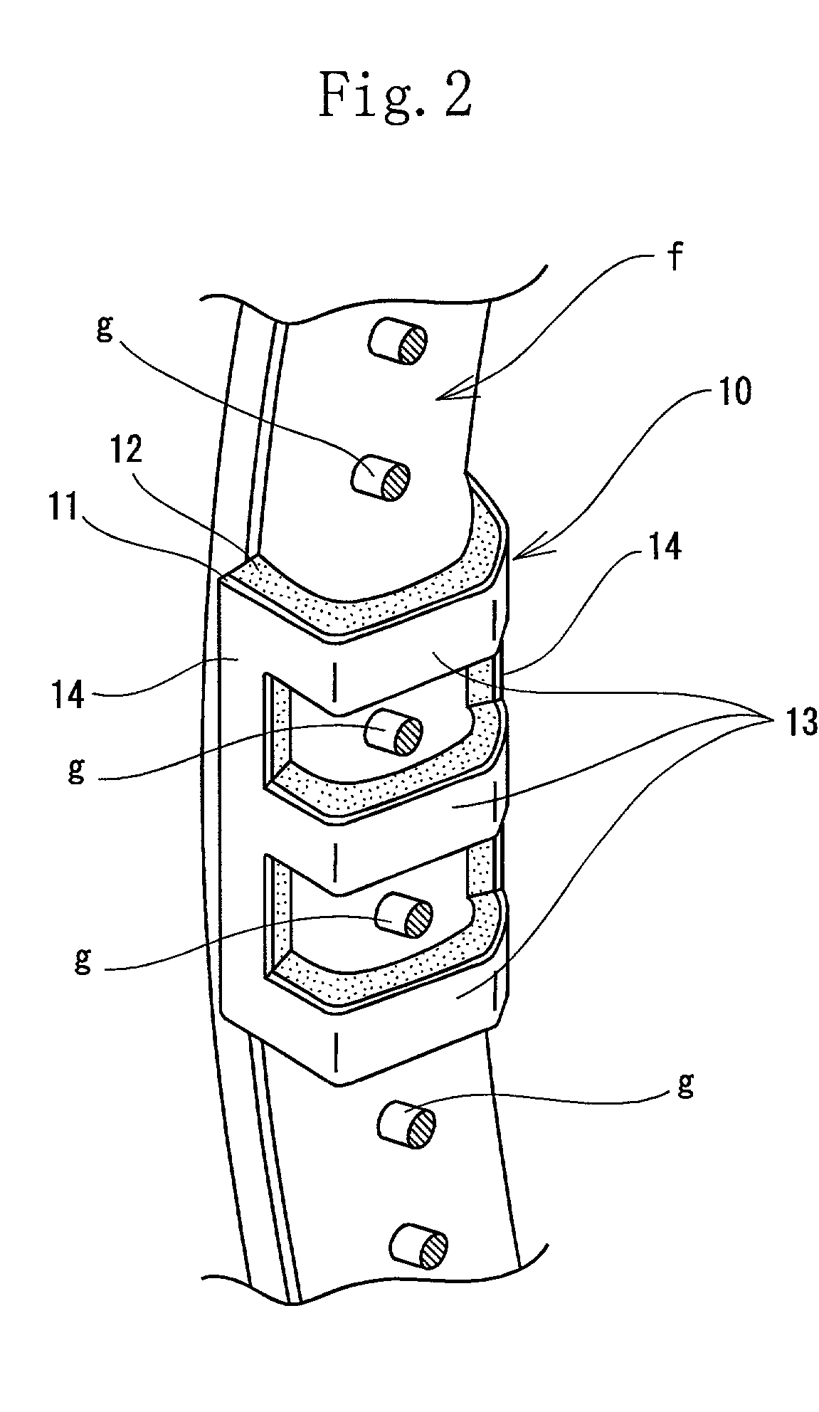
[0121] The material for the mass-adding part 11 and the viscoelastic part 12 and the method of producing the dynamic damper are the same as those of the example 1. But the length-to-breadth ratio was 0.64. The dynamic damper of the example 2 had the same configuration as that of the dynamic damper of the example 1. As shown in FIGS. 3A, 3B, and 3C, three U-shaped horizontal frames 13 were formed integrally with two long and narrow vertical frames 14 to form the dynamic damper in the shape of a lattice. The interval between the adjacent U-shaped horizontal frames 13 was 5.5 mm. The length of the long and narrow vertical frame 14 was 26 mm. The length of the U-shaped horizontal frame 13 was 41 mm. The dynamic damper 10a was fixed to the three and nine o'clock positions of the gut-stretched part of the racket frame with an adhesive agent.

example 3

[0122] The material of the mass-adding part 11 and the viscoelastic part 12 and the method of producing the dynamic damper were the same as those of the example 1. The length-to-breadth ratio was 0.9. As shown in FIGS. 9A, 9B, four U-shaped horizontal frames 13 were formed integrally with two long and narrow vertical frames 14b to form the dynamic damper in the shape of a lattice. The interval between the adjacent U-shaped horizontal frames 13 was 5.5 mm. The length of the long and narrow vertical frame 14b was 36.5 mm. The length of the U-shaped horizontal frame 13 was 41 mm. The dynamic damper 10b was fixed to the three and nine o'clock positions of the gut-stretched part of the racket frame with an adhesive agent.

example 4

[0123] The dynamic damper 10 of the example 2 was fixed to the five and seven o'clock positions of the gut-stretched part 1 of the racket frame with an adhesive agent.


PUM


Abstract

A dynamic damper (10) having a viscoelastic part (12) and a mass-adding part (11) laminated on the viscoelastic part (12). The dynamic damper (10) has a horizontal frame (13) and a vertical frame (14) disposed at both sides of the horizontal frame (13) in such a way that the horizontal frame (13) and the vertical frame (14) continuous with the horizontal frame (13) in the shape of a lattice. The horizontal frame (13) and the vertical frame (14) are integral with each other or separately provided in the shape of a lattice.

Description

[0001] The present invention relates to a dynamic damper and a dynamic damper-installed tennis racket for improving shock and vibration characteristic thereof which are generated when we hit a ball with the tennis racket.DESCRIPTION OF THE RELATED ART[0002] The dynamic damper (vibration-damping member) having a viscoelastic part and a mass-adding part connected to the viscoelastic part is often used to reduce and relieve shock and vibrations generated in sports ball-hitting goods and tools when they are used. In the tennis rackets disclosed in Japanese Patent Publication No.52-13455 and Japanese Patent Application Laid-Open Nos.52-156031 and 4-263876, the cantilevered dynamic damper having a load-applying material fixed thereto through the elastic material is installed on the tennis racket. The dynamic damper resonates with vibrations of the racket frame to damp its vibration.[0003] More specifically, in Japanese Patent Publication No.52-13455, as shown in FIG. 23, the cantilevered ...

Claims


Application Information

Patent Timeline
Patent Type & Authority Applications(United States)
IPC IPC(8): A63B49/035A63B60/02A63B60/54A63B102/02F16F15/02
CPCA63B49/04A63B59/0074A63B59/0092A63B2049/0211A63B2209/00A63B2049/0235A63B2049/0241A63B2049/0247A63B2059/0003A63B2049/0217A63B2049/0204A63B60/02A63B2049/0203A63B60/54A63B2049/0207A63B60/42A63B60/002
Inventor KANEMITSU, YUMI
Owner DUNLOP SPORTS CO LTD
Why Eureka
Try Eureka