Method, system, and computer program product for managing terrain rendering information

a technology of terrain and information management, applied in the field of computer generated terrain, can solve the problems of increasing complexity and size of terrain data, difficult terrain, and algorithms that have not been extended to large terrain areas with complex shapes, such as the earth's surface,

Inactive Publication Date: 2002-05-23
THERE
View PDF4 Cites 53 Cited by
  • Summary
  • Abstract
  • Description
  • Claims
  • Application Information

AI Technical Summary

Benefits of technology

[0034] One advantage of the present invention is that render blocks are managed to maintain terrain rendering information. Less individual triangle management is required compared to the approach used in the ROAM algorithm.
[0035] Another advantage is that the present invention can manage terrain data at interactive rates for a large terrain area having a complex shape, such as, a sphere. Terrain rendering management manages the allocation of render blocks to maintain active triangles and active textures for terrain data even when that terrain data potentially covers a large terrain area having a complex shape, such as, the Earth's surface.
[0036] In one embodiment, a terrain engine provides terrain primitive and texture information for rendering view-dependent scenes in frames updated at interactive rates (at rates of every several frames, every frame, or faster). Terrain data can have a topologically complex spherical shape covering a large data set such as a planet surface. Render blocks are managed and allocated, however, in a set of quad trees corresponding to six cube faces. In this way, primitives and textures for terrain are processed in render blocks at interactive frame rates by personal computer level graphics hardware even when terrain data covers a large terrain area having a complex shape, such as, the Earth's surface.
[0037] Further embodiments, features, and advantages of the present inventions, as well as the structure and operation of the various embodiments of the present invention, are described in detail below with reference to the accompanying drawings.
[0038] The accompanying drawings, which are incorporated herein and form a part of the specification, illustrate the present invention and, together with the description, further serve to explain the principles of the invention and to enable a person skilled in the pertinent art to make and use the invention.
[0039] FIG. 1 is a block diagram of a distributed terrain management system including a terrain administrator and remote terrain engines according to one embodiment of the present invention.

Problems solved by technology

Terrain is especially difficult because, inter alia, it does not naturally divide into separate parts and associated triangulation is view-dependent.
This is difficult as the complexity and size of the terrain data increases.
Such algorithms, however, have not been extended to a large terrain area having a complex shape, such, as the Earth's surface.
Accordingly, expensive work was performed to place individual triangles of a terrain optimally with respect to a scene being rendered.

Method used


Image

  • Method, system, and computer program product for managing terrain rendering information
  • Method, system, and computer program product for managing terrain rendering information
  • Method, system, and computer program product for managing terrain rendering information

Examples


example render

[0082] Example Render Blocks

[0083] Render Block Allocation Algorithm

[0084] Allocation Criteria

[0085] Routine for Finding a Distance Between Points on Different Cube Faces

[0086] Filling allocated Render Blocks

[0087] Texture Creation

[0088] Change of Reference Point Information

[0089] Example Render Block Allocation Algorithm Based on Block Budgets Assigned Per Level

[0090] Position Conversion

[0091] Converting a Position from 3-D to 2-D

[0092] Converting a Position from 2D to 3D

[0093] Converting a Position in 3D to 2D

[0094] Converting a Position from 2D to 3D

[0095] Example Graphics Implementations

[0096] Example Architecture

[0097] Host and Graphics Subsystem

[0098] Example Computer System

[0099] Conclusion

[0100] Overview

[0101] The present invention relates to the management of terrain rendering information. A method, system, computer program product, and computer data signal are provided for managing terrain rendering information. A method, system, computer program product, and computer data...

example environment

[0109] Example Environment

[0110] Embodiments of the present invention are described below with respect to example distributed terrain management and computer graphics environments.

[0111] These example environments, however, are illustrative and not necessarily intended to limit embodiments of the present invention. For example, the present invention can be used with any terrain data source on a stand-alone computer or a networked computer including, but not limited to, a terrain engine that allows terrain data covering the Earth's surface to be rendered, managed, updated, and / or administered at real-time interactive frame rates by consumer-level graphics hardware as described with respect to FIG. 1. In other embodiments, terrain data is simply obtained from user input, memory, a file or any other type of terrain data source.

[0112] Distributed Terrain Management System

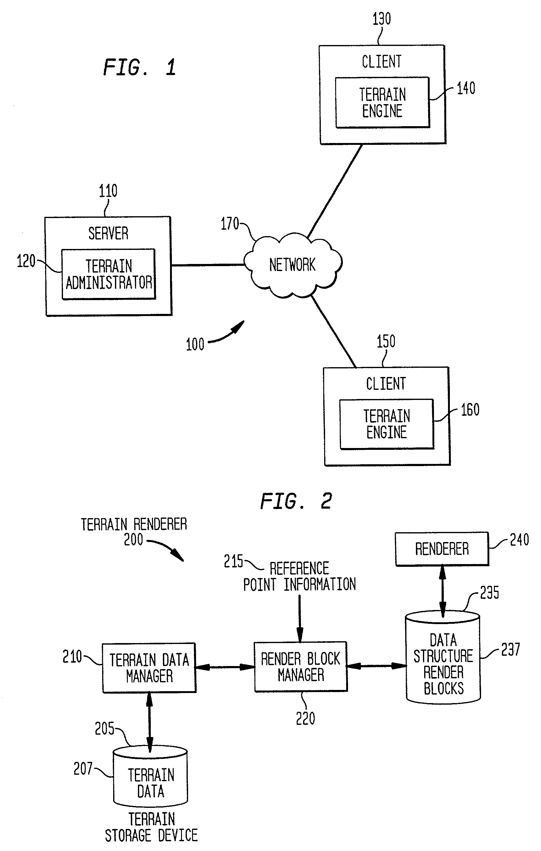
[0113] FIG. 1 is a block diagram of a distributed terrain management system 100.

[0114] Distributed terrain management...

example cube

[0155] Example Cube / Sphere Environment

[0156] In one embodiment of the present invention, a three-dimensional terrain topology of a virtual world is represented by a set of two-dimensional topologies. In general, general terrain calculations can be performed more simply and faster on a two-dimensional topology than a three-dimensional topology. FIG. 5 is a diagram that illustrates an example three-dimensional topology of a virtual world defined with respect to a sphere 510. A set of two-dimensional topologies defines cube faces of cube 520. Terrain defined in a coordinate space of the cube faces of cube 520 then approximates terrain defined in a coordinate space of sphere 510.

[0157] Cube 520 has six faces which can be arranged in any number of layouts. FIG. 6 shows one example layout 615. In layout 615, cube faces 0-5 are arranged such that cube faces 0, 2, 1, 3 are arranged in a row side-by-side with cube face 4 adjoining cube face 2, and cube face 5 adjoining cube face 1. Cube face...


PUM


Abstract

The present invention provides a method, system, and computer program product for managing terrain rendering information. The terrain rendering information includes a data structure of render blocks. The data structure represents a three-dimensional terrain topology of a virtual world with a set of two-dimensional terrain topologies. Each render block includes primitives that define samples of a respective area of terrain to be rendered. A render block manager manages the allocation of render blocks in the data structure based on current reference point information and allocation criteria. Terrain data at higher levels of detail (that is, a greater resolution) is kept closer to the reference point information by adding and removing appropriate render blocks. In this way, appropriate terrain rendering information is maintained efficiently in the data structure during movement of a reference point. Terrain data to be rendered is managed at interactive rates for a large terrain area having a complex shape, such as, a sphere.

Description

[0001] This application claims the benefit of priority to the following commonly-owned and co-pending applications:[0002] 1. Method, System, and Computer Program Product for Managing Terrain Rendering Information, U.S. Provisional Application, Application No. 60 / 289,584, filed May 9, 2001 by M. Handley et al. (incorporated in its entirety herein by reference);[0003] 2. Method, System, and Computer Program Product for Managing, Rendering and / or Administering Terrain Data, Application Ser. No. 09 / 560,564, filed Apr. 28, 2000 by B. Werther et al. (incorporated in its entirety herein by reference); and[0004] 3. Synthetic Terrain Generation Including Fractal Terrain Generation and Terrain-Type Data Generation, Application Ser. No. 09 / 560,886, filed Apr. 28, 2000 by W. Harvey et al. (incorporated in its entirety herein by reference).[0005] 1. Field of the Invention[0006] The present invention relates to computer-generated terrain.[0007] 2. Background Art[0008] Terrain visualization at int...

Claims


Application Information

Patent Timeline
Patent Type & Authority Applications(United States)
IPC IPC(8): G06T15/00
CPCG06T17/05G06T15/005
Inventor HANDLEY, MALCOLMHARVEY, WILLIAM DAVIDWERTHER, BENJAMIN M.
Owner THERE
Why Eureka
Try Eureka