
Adjustment pipe for fuel injection valve, and press-fitting structure and press-fitting method for the same

a technology of fuel injection valve and adjustment pipe, which is applied in the direction of pipe elements, liquid/fluent solid measurement, machines/engines, etc., can solve the problems of reducing the dimension accuracy of the components in the fuel injection valve, limiting the generation of adhesion, and excessive press-fitting load

Inactive Publication Date: 2002-05-30
DENSO CORP
View PDF15 Cites 14 Cited by
  • Summary
  • Abstract
  • Description
  • Claims
  • Application Information

AI Technical Summary

Benefits of technology

[0007] In is an another object of the present invention to provide an adjustment pipe being press-fitted into a cylindrical housing in a fuel injection valve, which reduces a difference of press-fitting load of the adjustment pipe, readily performs a fine adjustment of a press-fitting amount of the adjustment pipe, and restricts a compression deformation of components of the fuel injection valve.
[0008] It is a further another object of the present invention to provide a press-fitting method for press-fitting an adjustment pipe into a cylindrical housing for a fuel injection valve, by which a high-quality and trustworthy fuel injection valve can be readily manufactured.
[0009] According to the present invention, in a press-fitting structure of an adjustment pipe for adjusting a compression amount of a spring member for biasing a valve member, a lubricating material is adhered or formed on at least one of an outer peripheral surface of the adjustment pipe and an inner peripheral surface of a cylindrical housing. Therefore, when the adjustment pipe is press-fitted into the cylindrical housing, because the lubricating material is placed between the adjustment pipe and the cylindrical housing, it can prevent a direct pressure-contact between both metal press-contacting surfaces of the adjustment pipe and the cylindrical housing, and it can restrict the adhesion from being generated. In addition, because the lubricating material is placed between the adjustment pipe and the cylindrical housing, the lubricating material does not increase a press-fitting load. Accordingly, a difference of the press-fitting load of the adjustment pipe can be made smaller, a fine adjustment of the press-fitting amount of the adjustment pipe can be made simple, and compression deformation due to an excessive press-fitting load can be restricted. Accordingly, when the press-fitting structure of the adjustment pipe is used for a fuel injection valve, a dimension accuracy of the fuel injection valve can be sufficiently maintained.
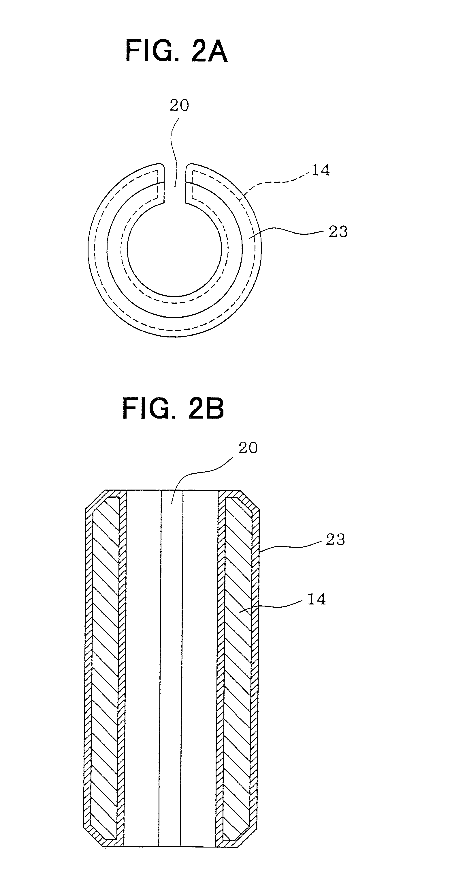
[0010] Preferably, each of the adjustment pipe and the cylindrical housing is made of stainless steel, and an oxalate film is formed on at least one of the outer peripheral surface of the adjustment pipe and the inner peripheral surface of the cylindrical housing. Alternatively, a phosphate film is formed on at least one of the outer peripheral surface of the adjustment pipe and the inner peripheral surface of the cylindrical housing. In this case, because the oxalate film or the phosphate film is not removed even when the adjustment pipe is press-fitted into the cylindrical housing, the dimension accuracy of the fuel injection valve can be readily maintained.
[0011] According to a press-fitting method for press-fitting an adjustment pipe into a cylindrical housing for a fuel injection valve, after a lubricating material is formed or adhered on at least one of an outer surface of the adjustment pipe and an inner surface of the cylindrical housing, the adjustment pipe is temporarily press-fitted the into the cylindrical housing, and the press-fitted amount of the adjustment pipe into cylindrical housing is adjusted to a predetermined amount. In addition, a test liquid is supplied into a temporarily assembled fuel injection valve, and a confirmation operation of a fuel injection amount from the fuel injection port is repeated by opening and closing the valve member while the adjustment pipe being gradually press-fitted into the cylindrical housing. Accordingly, a stable fixing load of the adjustment pipe can be obtained, and a high-quality fuel injection valve can be readily manufactured.

Problems solved by technology

Therefore, the press-fitting load is excessively increased, components such as the cylindrical housing may be deformed, and dimension accuracy of the components in the fuel injection valve may be decreased.
Therefore, when the adjustment pipe is press-fitted into the cylindrical housing, because the lubricating material is placed between the adjustment pipe and the cylindrical housing, it can prevent a direct pressure-contact between both metal press-contacting surfaces of the adjustment pipe and the cylindrical housing, and it can restrict the adhesion from being generated.
In addition, because the lubricating material is placed between the adjustment pipe and the cylindrical housing, the lubricating material does not increase a press-fitting load.

Method used


Image

  • Adjustment pipe for fuel injection valve, and press-fitting structure and press-fitting method for the same
  • Adjustment pipe for fuel injection valve, and press-fitting structure and press-fitting method for the same
  • Adjustment pipe for fuel injection valve, and press-fitting structure and press-fitting method for the same

Examples


Embodiment Construction

[0019] Preferred embodiments of the present invention will be described hereinafter with reference to the accompanying drawings.

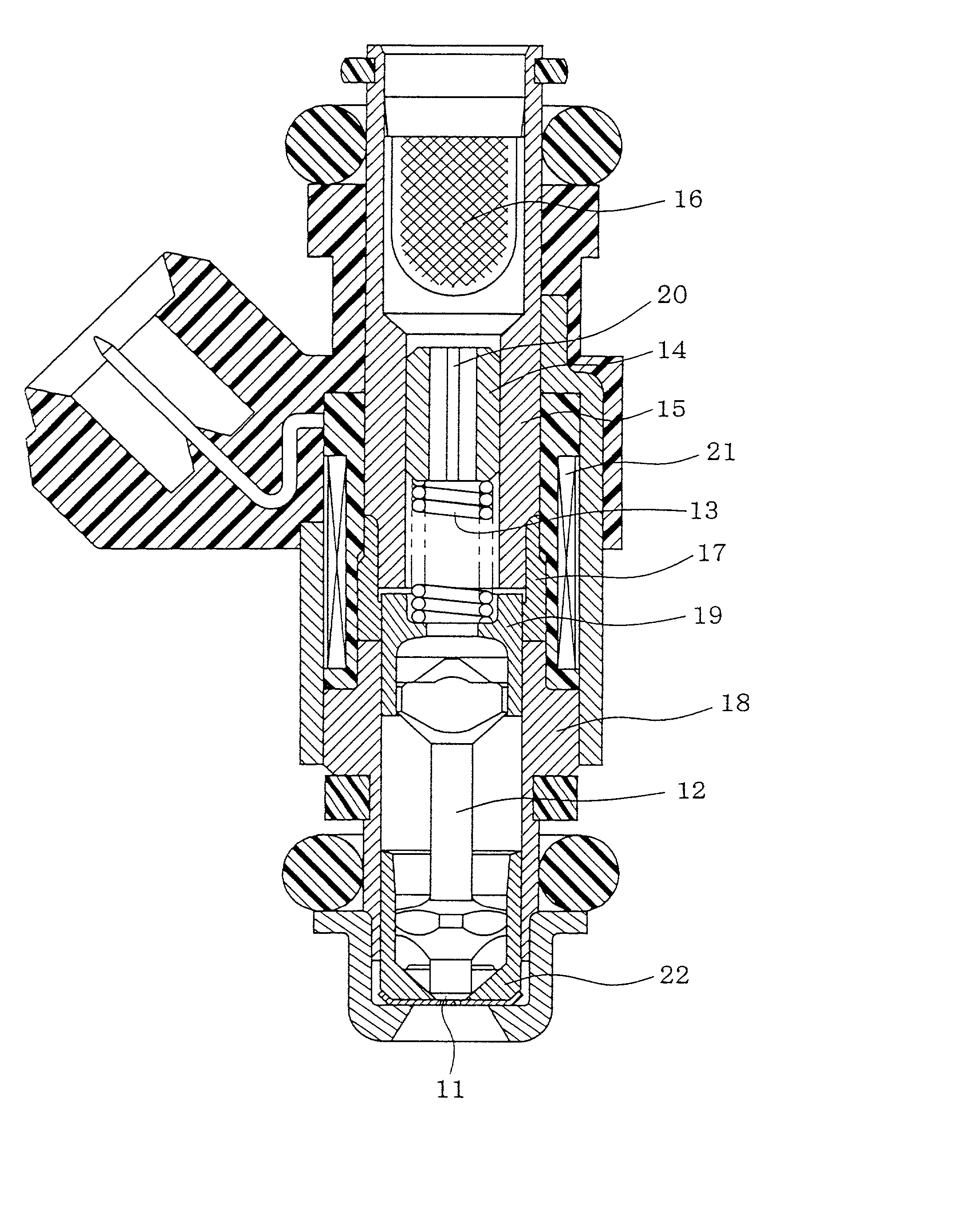
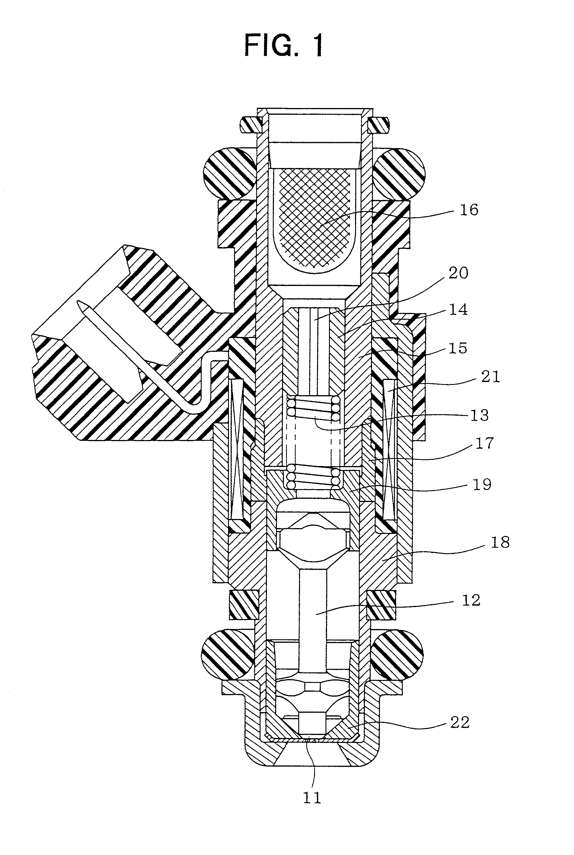
[0020] A first preferred embodiment of the present invention will be now described with reference to FIGS. 1-5. As shown in FIG. 1, in a fuel injection valve, a cylindrical housing 15 is made of a magnetic stainless steel, and is used as a fixed magnetic core. A fuel filter 16 is disposed at an upper side in the cylindrical housing 15. A middle pipe 17 made of a non-magnetic material is attached to a lower side portion of the cylindrical housing 15 by brazing, and a magnetic valve body 18 having therein a valve member 12 is bonded to a lower end of the middle pipe 17 by brazing. The valve member 12 is disposed to open and close a fuel injection port 11 from which fuel is injected. A hollow movable valve member 19 connected to a top end part of the valve 12 is disposed opposite to a bottom surface of the cylindrical housing 15, so that the movable core 19 an...


PUM

PropertyMeasurementUnit
Forceaaaaaaaaaa

Abstract

In a fuel injection valve, an adjustment pipe made of stainless steel and for adjusting a compression amount of a spring biasing a valve member is press-fitted into a cylindrical housing made of stainless steel, and a fuel injection amount is adjusted by adjusting a spring force of the spring in accordance with a press-fitted amount of the adjustment pipe. The adjustment pipe is immersed in an oxalic acid solution so that an oxalate film is formed thereon before being press-fitted into the cylindrical housing. Therefore, the oxalate film prevents a direct press-contact between an outer peripheral surface of the adjustment pipe and an inner peripheral surface of the cylindrical housing.

Description

[0001] This application is related to Japanese Patent Application No. 2000-367754 filed on Nov. 29, 2000, the contents of which are hereby incorporated by reference.[0002] 1. Field of the Invention[0003] The present invention relates to an adjustment pipe for adjusting a compression amount of a spring biasing a valve member in a fuel injection valve, and a press-fitting structure and a press-fitting method of the adjustment pipe.[0004] 2. Description of Related Art[0005] In a fuel injection valve, generally, a valve member (needle valve) for opening and closing a fuel injection port is biased by a spring, and a spring force of the spring is adjusted by an adjustment pipe disposed in a cylindrical housing. For fitting the adjustment pipe within the cylindrical housing, a caulking method or a press-fitting method may be used. In the caulking method, an outer radial dimension of the adjustment pipe is made slightly smaller than an inner radial dimension of the cylindrical housing, and ...

Claims


Application Information

Patent Timeline
IPC IPC(8): F02M51/06F02M61/20F02M69/46
CPCF02M51/0671F02M61/205Y10T29/53Y10T29/49886Y10T29/49826Y10T29/49885Y10T29/493Y10T29/49764Y10T29/49888Y10T29/49412Y10T137/0491Y10T137/598Y10T137/5987
Inventor SUMIYA, SADAOYAMADA, HIROATSU
Owner DENSO CORP
Learn More