Virtual stent making process based upon novel enhanced plate tectonics derived from endoluminal mapping

a technology of enhanced plate tectonics and which is applied in the field of virtual stent making process based upon novel enhanced plate tectonics derived from endoluminal mapping, can solve the problems of difficult comparison of the safety and efficacy of endovascular procedures, the risk of embolic events in patients with unstable (ulcerating) plaque morphologies, and the only suitable or even unsuitable stent for implantation of conventional s

Inactive Publication Date: 2002-06-06
HUPP THOMAS
View PDF0 Cites 94 Cited by
  • Summary
  • Abstract
  • Description
  • Claims
  • Application Information

AI Technical Summary

Benefits of technology

[0007] Likewise, as techniques and devices having peripheral vascular applications evolve, the carotid arteries have become prominent as housing target stenotic lesions. This is further bolstered by the ongoing trend that extends patients' viability longer exposing greater number of patients to the need for carotid artery intervention at some point in their medical history.

Problems solved by technology

Balancing against the strong need for alternate therapies is the risk of embolic events feared in those patients having unstable (ulcerating) plaque morphologies.
This makes comparison of the safety and efficacy of endovascular procedures difficult to compare with CEA.
To date, it is respectfully proposed that it has turned out in practice that conventional stents are only poorly suitable or even not suitable for implantation in the carotid artery for treatment of a constriction (stenosis) of the carotid artery (Arteria carotis).
Conventional stents in tube form thus fit poorly, since they have either a diameter that is too small at one end or too large at the other end.
This stent in fact has an enlarged radial opening in the region of the vessel bifurcation, but is formed as a simple tube and is thus not suitable for implantation in the carotid artery.

Method used


Image

  • Virtual stent making process based upon novel enhanced plate tectonics derived from endoluminal mapping
  • Virtual stent making process based upon novel enhanced plate tectonics derived from endoluminal mapping
  • Virtual stent making process based upon novel enhanced plate tectonics derived from endoluminal mapping

Examples


examples

Materials & Methods

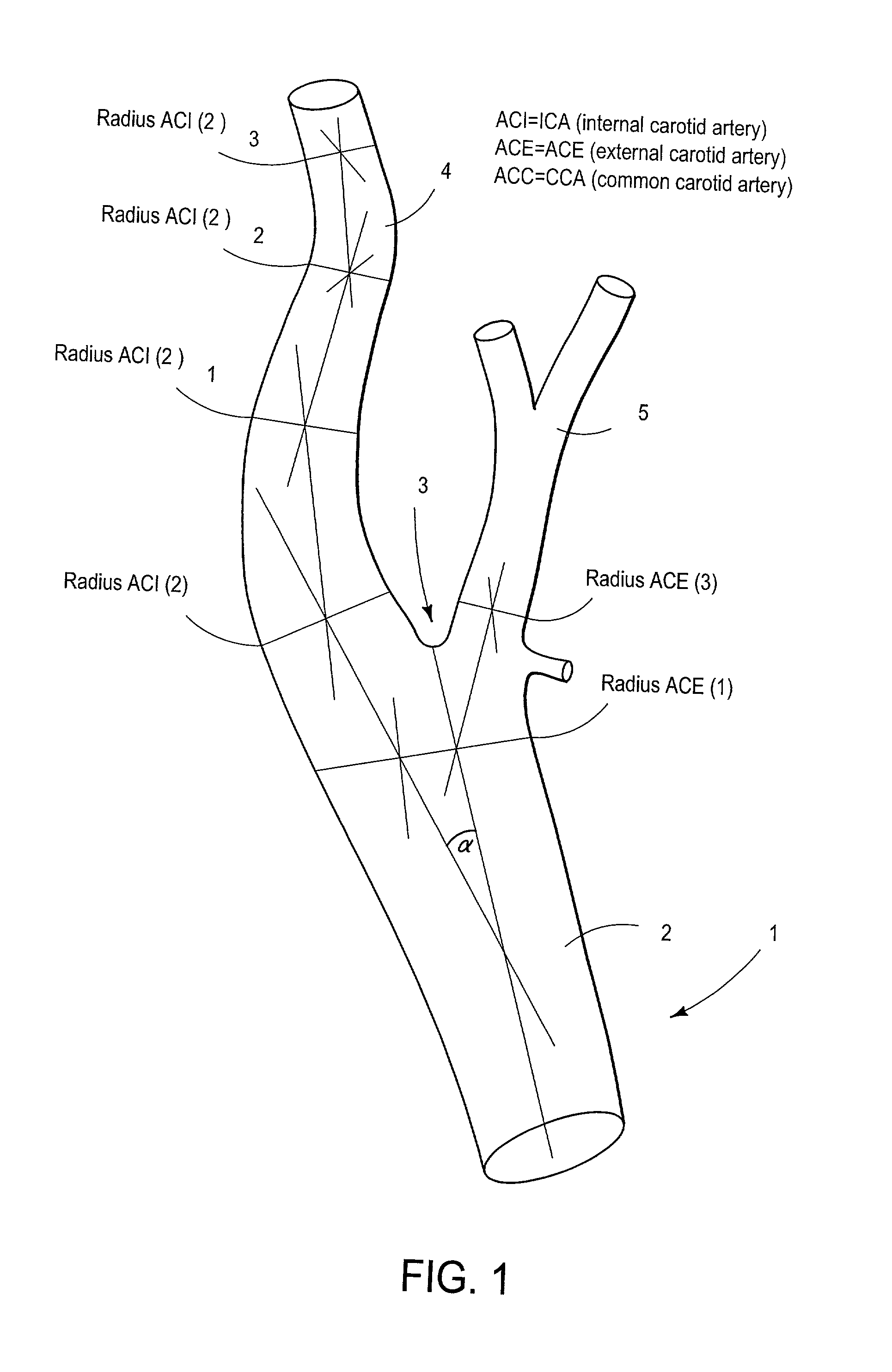
[0055] 118 carotid bifurcation samples were harvested from autopsies and respective packets of individuated data points arrayed in a specialized database (EXCEL.RTM., Microsoft Corporation, Redmond, Wash. State, U.S.A.) including relevant information from the autopsy register about the cause of death and underlying illnesses in addition to sample side (right versus left) and all height and weight data.

[0056] Casts were prepared from the harvested vessels by suspending them, suitabley prepared at a suspension facility, in the direction of flow. The vessels were then drained with a fast-hardening plastic (PALADUR R, Heraeus Kulzer GmbH, Wehrheim, Germany), and cured for 1 / 3 of an hour at approximately 23 degrees Celcius. The resulting hardened cast preparations were compared with the harvested vessels, which were preserved in formalin, cataloged and anterior / posterior projections documented photographically.

[0057] Calliper gauge measurements were taken (MITUTOYO.RTM...

second embodiment

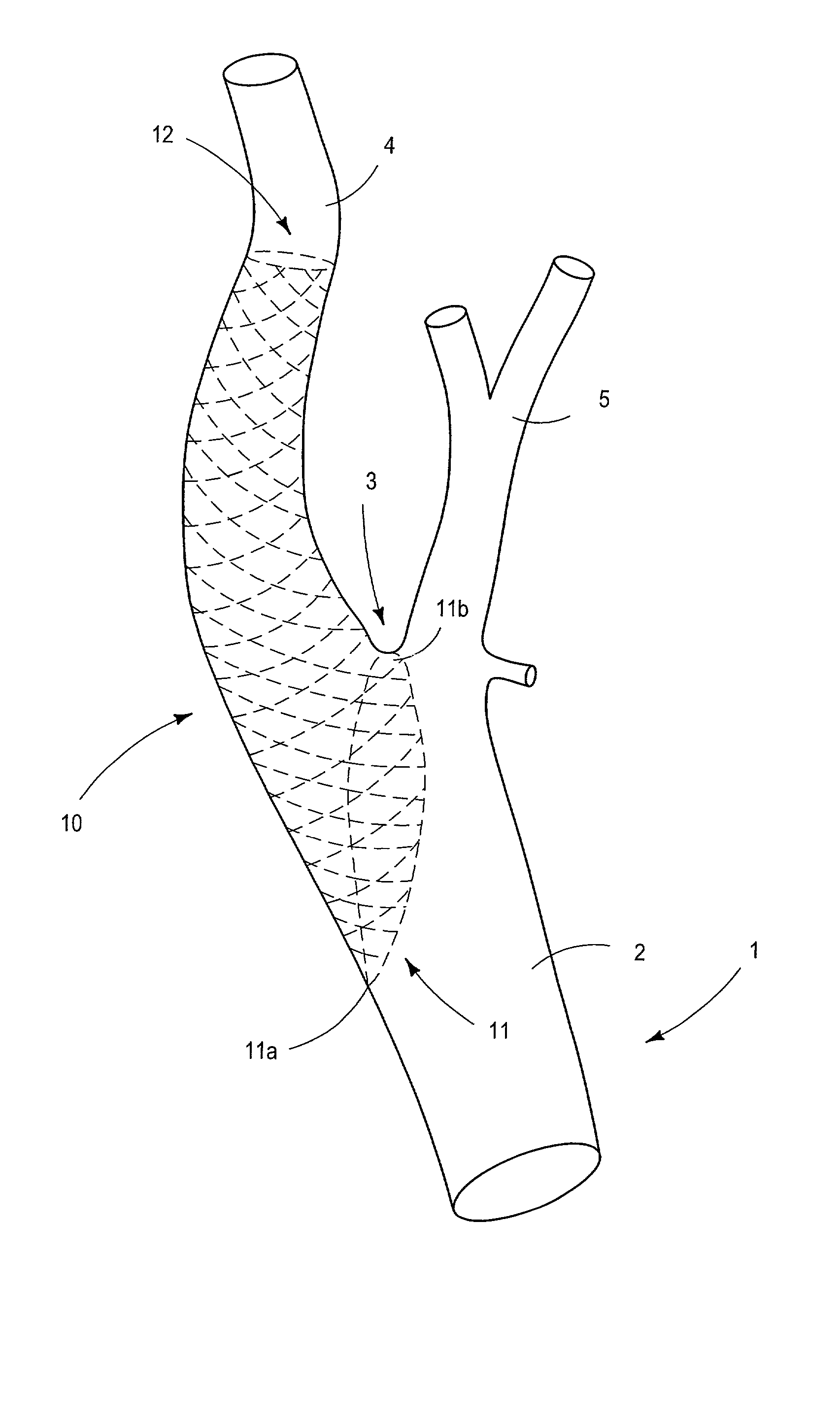
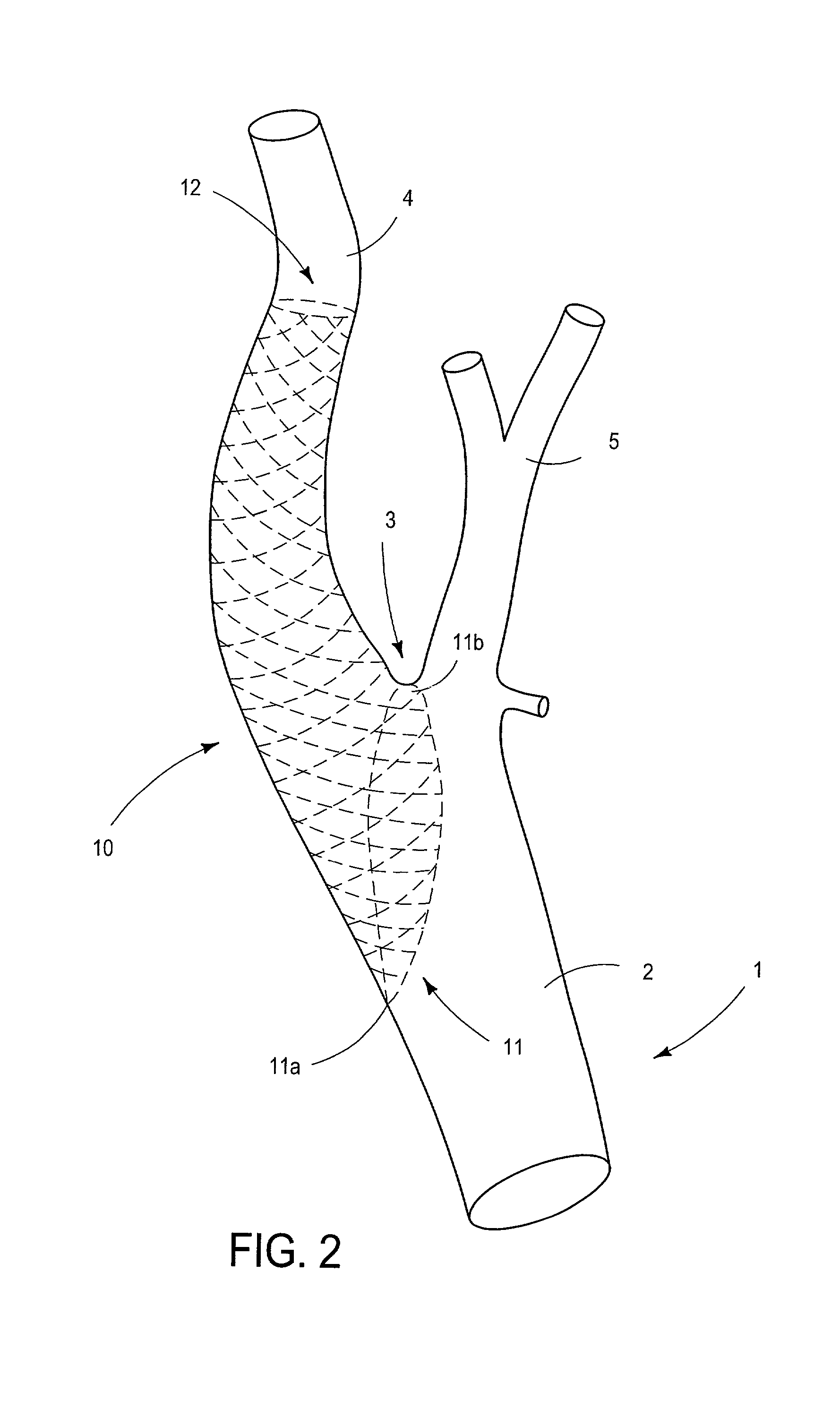
[0087] FIG. 6 shows a schematic view of stent 20 made from cast made from a set of data points from carotid arteries modeled on a computer-aided design system. The reference designators denote the same elements.

[0088] Turning now to FIG. 7 a digital photographic image comprising a virtual stent according to an embodiment of the process of the present invention, the same being generated by plotting at least about 500,000 data points within a carotid application is shown which corresponds to the schematic in FIG. 6.

[0089] FIG. 8 likewise is a digital photographic image of a plan view of an embodiment schematically mapping a virtual stent with computer-aided-design with respect to an embodiment as shown in FIG. 3 above. It is noted that applicant contemplates the use of any number of different stent scaffolding materials or patterns as discussed above.

[0090] FIG. 9 is also a digital photographic image of a rotated and carotid bifurcation orientated view of an embodiment schematically m...


PUM


Abstract

The present invention concerns a process for making a virtual stent for implantation into a body lumen. A particularly preferred embodiement is optmized for emplacement and indwelling in the internal carotid artery, with a lower end and an upper end wherein the radius decreases from lower end to upper end, and includes "trumpet-like' or parabolic elements abutting facultative apertures. Generally, computer-aided-design derived stent has a tectonic structure in the form of angles and curvatures adapted to the course of a desired lumen. For example, the internal carotid artery whereby lower end in the region of the outlet of internal carotid artery is formed as an ovaloid recess provided in the region of the outlet of the external carotid artery.

Description

[0001] This application claims full Paris convention priority rights from DE10040630.0 filed Aug. 16, 2000, and the U.S. Provisional Patent Application Serial No. 60 / 227,070 filed Aug. 22, 2000 entitled STENT ZUR IMPLANTATION IN DIE HALSSCHLAGADER. Likewise, the instant application is a continuation in part of PCT / US01 / 24656, lodged Aug. 4, 2001, each of the same authored by the present inventor, with the latter including EDWARDS LIFESCIENCES LLC as co-applicant.[0002] The present invention relates to novel apparatus and processes for maintaining patency of body lumens. In particular, the present invention supplies novel enhanced customized, optimized or otherwise individuated stents, useful for example in the carotid artery--wherein a generally conical / `trumpet-like` / or parabolic shaped member having free ends--is emplaced into the native vessel to provide for enhanced blood flow.[0003] Attention is called to the following European and PCT patent applications, publications, and Uni...

Claims


Application Information

Patent Timeline
Patent Type & Authority Applications(United States)
IPC IPC(8): A61F2/90
CPCA61F2/90A61F2/856
Inventor HUPP, THOMAS
Owner HUPP THOMAS
Why Eureka
Try Eureka