Thin film magnetic head and method of manufacturing the same

a thin film, magnetic head technology, applied in the direction of head surface, head with metal sheet core, instruments, etc., can solve the problems of electromagnetic conversion characteristics degraded, loss rose, and unsuitable mass production

Inactive Publication Date: 2002-06-13
TDK CORPARATION
View PDF20 Cites 1 Cited by
  • Summary
  • Abstract
  • Description
  • Claims
  • Application Information

AI Technical Summary

Problems solved by technology

One of the problems in the above conventional techniques is not suitable for mass-production since a complete thin film magnetic head is processed.
The other problem is that in employing the above processing method, for protecting, from oxidization and erosion, the end of the magnetic film constituting the pole part exposed to the bottom face of the thus dug depressed portion, a protective film is required to be formed on the whole surface opposite to the recording medium containing the ABS and the depressed portion.
As the thickness of the protective film is increased, the amount of the material to be stuck to the ABS of which the protective film is made is obviously increased, so that spacing loss is rose up and thereby electromagnetic conversion characteristics are degraded.
The above problems is not only peculiar to the digging process to narrow the track width, but also is brought about to the case of digging up the area containing the pole part.

Method used


Image

  • Thin film magnetic head and method of manufacturing the same
  • Thin film magnetic head and method of manufacturing the same
  • Thin film magnetic head and method of manufacturing the same

Examples


first embodiment

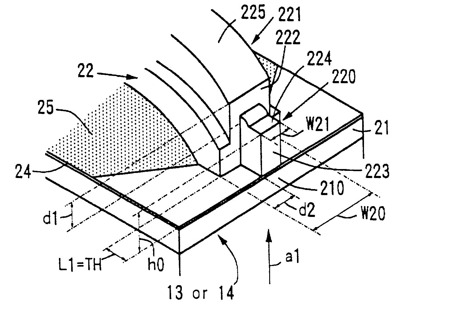
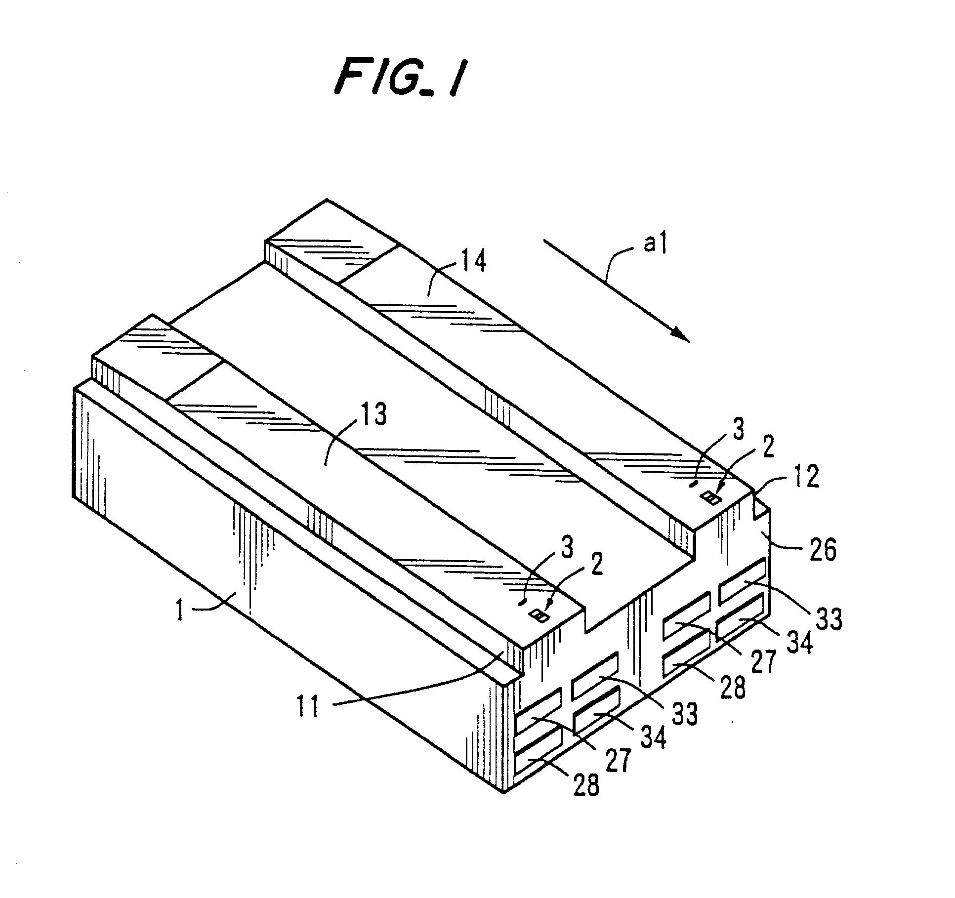
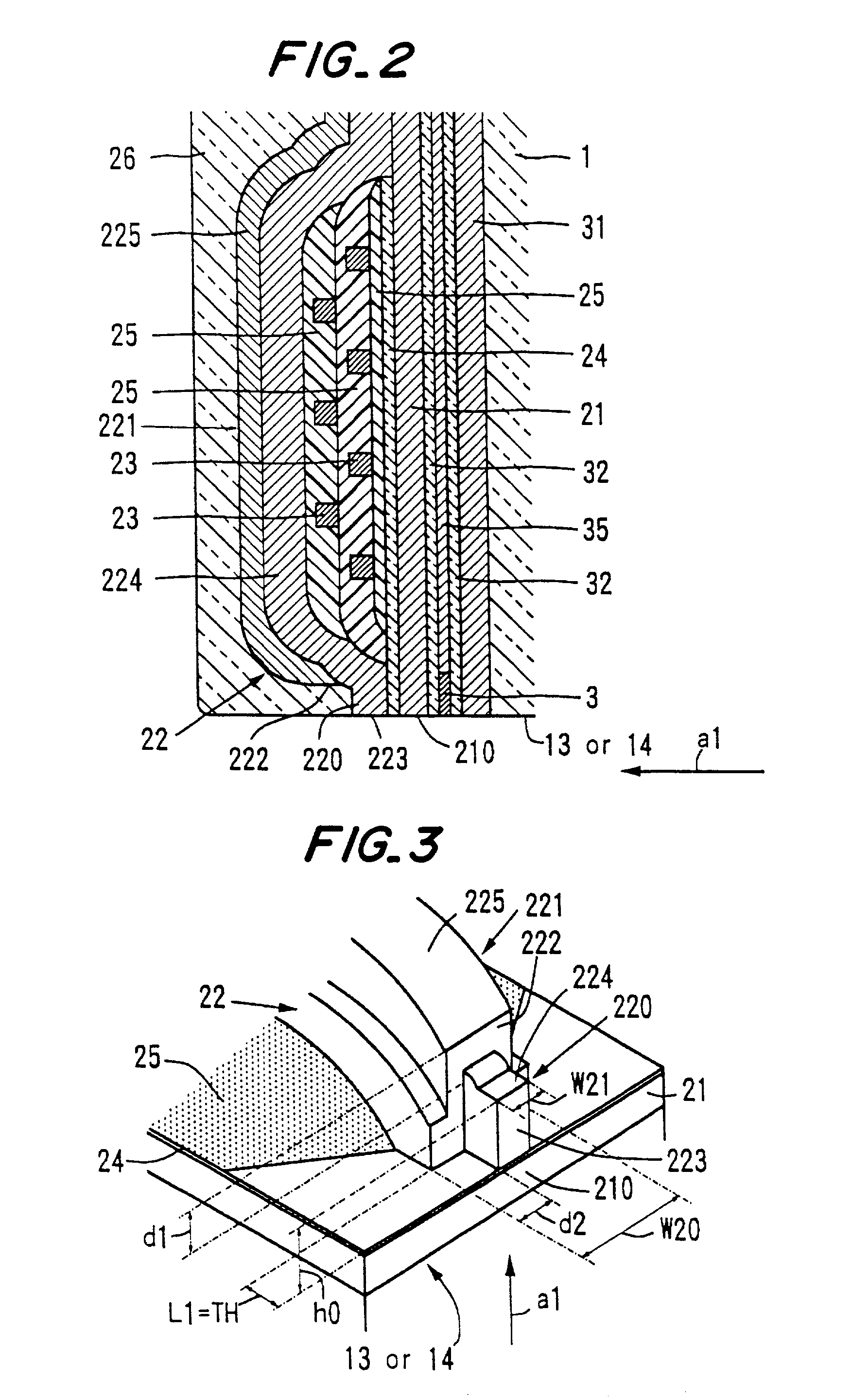
[0079] FIG. 1 is a perspective view showing the thin film magnetic head according to the present invention, FIG. 2 is a cross sectional view showing the thin film magnetic head of FIG. 1, FIG. 3 is a partially enlarged perspective view showing the structure of the pole part in the thin film magnetic head shown in FIGS. 1 and 2, and FIG. 4 is a partially enlarged perspective view showing the end of the pole part in the thin film magnetic head shown in FIGS. 1 and 2. For clarifying the features of the present invention, in these figures, the dimension of each part of the thin film magnetic head is different from that in the practical one. The thin film magnetic head in this embodiment has a slider 1, an inductive-type thin film magnetic head 2 formed so as to be supported by the slider, a magnetoresistive-type thin film magnetic head 3 and two pairs of composite type thin film magnetic head, of which the entire part is covered with a protective layer 26.

[0080] Rail parts 11 and 12 are...

second embodiment

[0109] FIG. 6 is a cross sectional view showing the thin film magnetic head according to the present invention, and FIG. 7 is a perspective view enlargedly showing the pole part of the thin film magnetic head shown in FIG. 6. The similar parts in the figures to ones in FIGS. 1 to 4 are depicted by the same references. In this embodiment, the yoke forefront surface 222 of the second magnetic film 22 rises up on the insulated film 25. In this case, since a point of a Throat Height "0" is defined as the periphery of the insulated film 25 which is starting point of the rising up of the second pole part 220, the Throat Height (TH) is a distance to the periphery of the insulated film 25 from the pole forefront surface 223.

[0110] In this embodiment, since the yoke forefront surface 222 is positioned nearby the Throat Height "0", a sufficient magnetic flux can be supplied to the throat Height "0". Thus, the overwrite characteristic can be much enhanced.

third embodiment

[0111] FIG. 8 is a perspective view showing the thin film magnetic head according to the present invention. The similar parts in the figures to ones in FIGS. 1 to 4 are depicted by the same references. The thin film magnetic head shown in thin embodiment has depressed portions 41 and 42. The depressed portions 41 and 42 are formed in the removed part of the gap film 24 in the edge portion composed of the yoke forefront surface 222 and the second pole part 220. Moreover, the portions have a depth of hi which partially reduces the surface of the first magnetic film 21. The depressed portions 41 and 42 are positioned in the both side of the first pole part 210, respectively. The yoke forefront surface 222 of the second magnetic layer 22 is positioned on the gap film 24 or the insulted layer 25 in the outside of the depressed portions 41 and 42.

[0112] The above structure exhibits the same operation-effect as one in the embodiment shown in FIGS. 1 to 4. Moreover, the structure can define...


PUM

PropertyMeasurementUnit
widthaaaaaaaaaa
thicknessaaaaaaaaaa
thicknessaaaaaaaaaa

Abstract

A first magnetic film, a gap film, a thin film coil supported by a insulated film and a second magnetic film are formed in turn. The second magnetic film has a pole part opposite to the first magnetic film via the gap film and a yoke part extending backward from the pole part to be magnetically connected to the first magnetic film. The forefront surface of the yoke part is receded from an air bearing surface. The pole part of the second magnetic film has a step d1 in a running direction of a magnetic recording medium and a step d2 in the perpendicular direction to the running direction within the yoke forefront surface and its periphery as is viewed from the yoke forefront surface. A protective film embeds the steps d1 and d2, and covers an inductive type thin film magnetic head element entirely. Thereby, without debasing the overwrite characteristic when the pole part is miniaturized, a thin film magnetic head having a narrowed track width can be provided.

Description

[0001] 1. Field of the Invention[0002] This invention relates to a thin film magnetic head and a method for manufacturing the same usable for a magnetic recording and reading device such as a magnetic disk device.[0003] 2. Related Art Statement[0004] For realizing a high density recording in a magnetic disk device, a recording track width to be wrote by a thin film magnetic head has become extremely narrower to, for example, not more than 1.0 .mu.m. A width of a pole part in the thin film magnetic head is required to be narrower for obtaining such an extremely narrow track-width, and as its means, it is known that an air bearing surface (hereinafter, abbreviated to "ABS") of a slider opposite to a magnetic recording medium is processed. In the case of such a technique to obtain the extremely narrow track-width, the surface of the slider opposite to the magnetic recording medium is polish-processed, etc., to form a gap having a given depth, and thereafter the area containing the magn...

Claims


Application Information

Patent Timeline
Patent Type & Authority Applications(United States)
IPC IPC(8): G11B5/31G11B5/39
CPCB82Y10/00Y10T29/49052G11B5/3106G11B5/3116G11B5/313G11B5/3133G11B5/3146G11B5/3163G11B5/3909G11B5/3967Y10T29/49043Y10T29/49044Y10T29/49046Y10T29/49048B82Y25/00
Inventor KAMIJIMA, AKIFUMI
Owner TDK CORPARATION
Why Eureka
Try Eureka