System for sensing the motion or pressure of a fluid

a fluid motion and fluid technology, applied in the field of systems for sensing the motion or pressure of fluids, can solve the problems of not being able to integrate into small electronic systems, not being able to meet the needs not being able and being difficult to meet the needs of small electronic systems. , to achieve the effect of reducing the cost of manual electronic assembly, and improving the accuracy of measuremen

Inactive Publication Date: 2002-06-27
HONEYWELL INT INC
View PDF0 Cites 112 Cited by
  • Summary
  • Abstract
  • Description
  • Claims
  • Application Information

AI Technical Summary

Problems solved by technology

They have been bulky, expensive, quite large and not suitable for integration into small electronic systems.
There has also been a lack of flexibility in design preventing incorporation into a variety of subsystems.
While these examples are improvements over prior art, they still require manual electronic assembly at high cost and low throughput.
There is a clear lack of a small sensor, p

Method used


Image

  • System for sensing the motion or pressure of a fluid
  • System for sensing the motion or pressure of a fluid
  • System for sensing the motion or pressure of a fluid

Examples


Embodiment Construction

[0035] The present invention provides an apparatus or system for sensing or measuring the motion of a fluid. For example, embodiments of the present invention may be used to measure flow rate. The present invention generally measures mass flow rate (units of mass per unit of time) more directly than volumetric flow rate (units of volume per unit of time). This is because the present invention directly measures heat transfer, which is more closely proportional to mass flow rate. However, embodiments of the present invention may also be used to measure or calculate volumetric flow rate or pressure (force per unit of area). For instance, volumetric flow rate is approximately proportional to mass flow rate where pressure is nearly constant. In addition, flow rate is generally related to pressure differential (i.e. pressure drop across the present invention). These parameters can be used to calculate other values as well, as would be understood by a skilled artisan.

[0036] In many applica...


PUM


Abstract

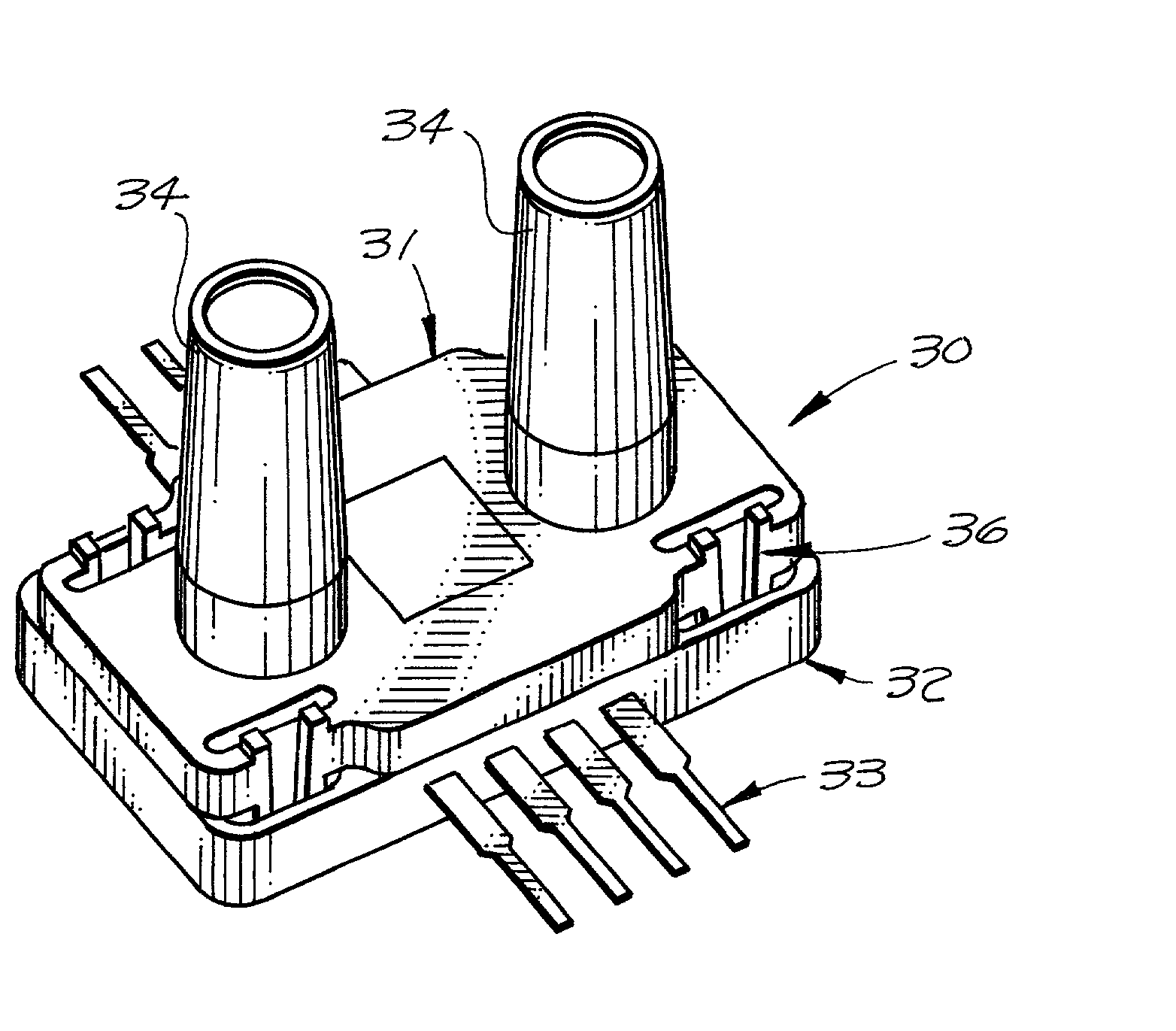
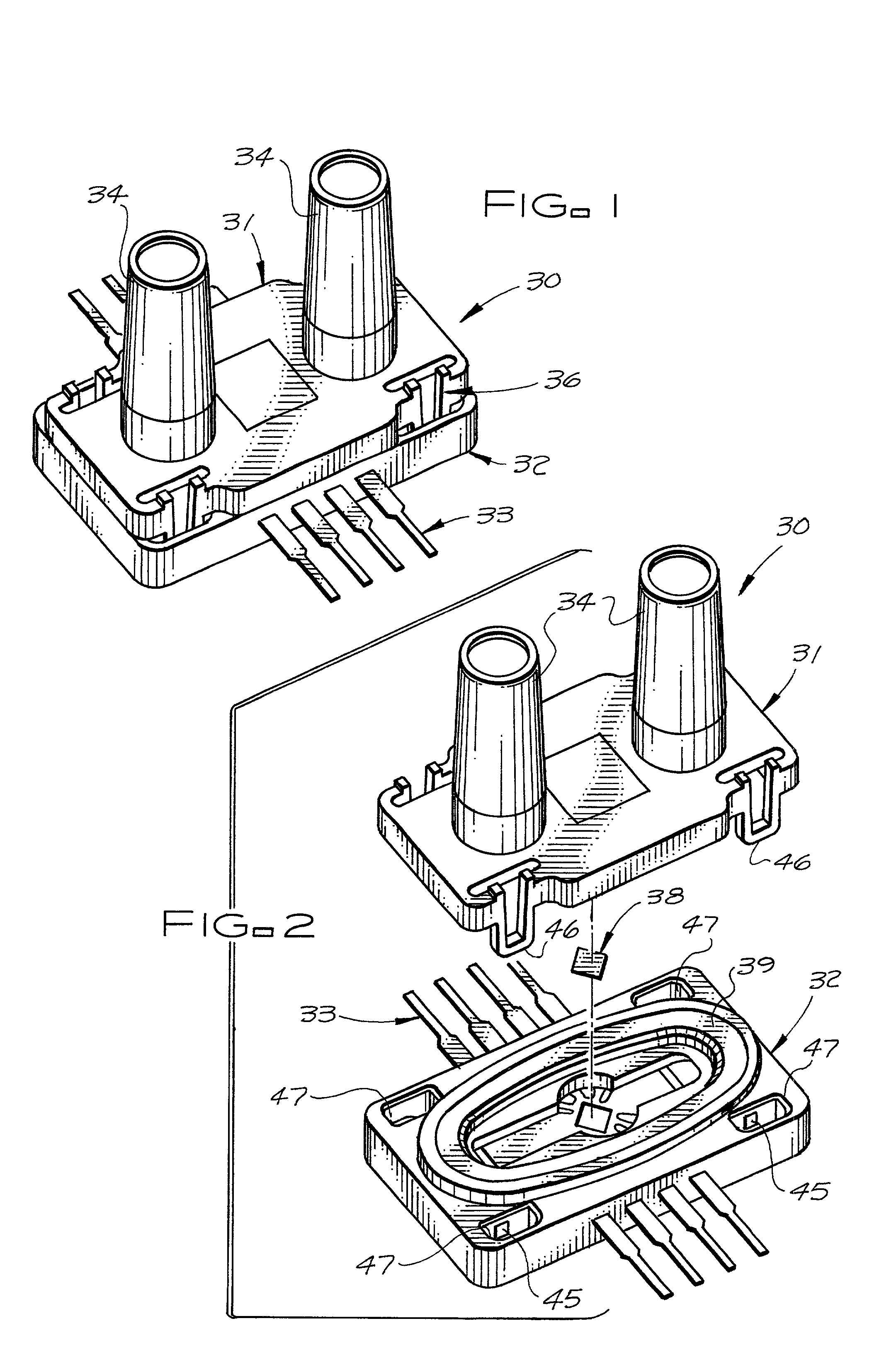
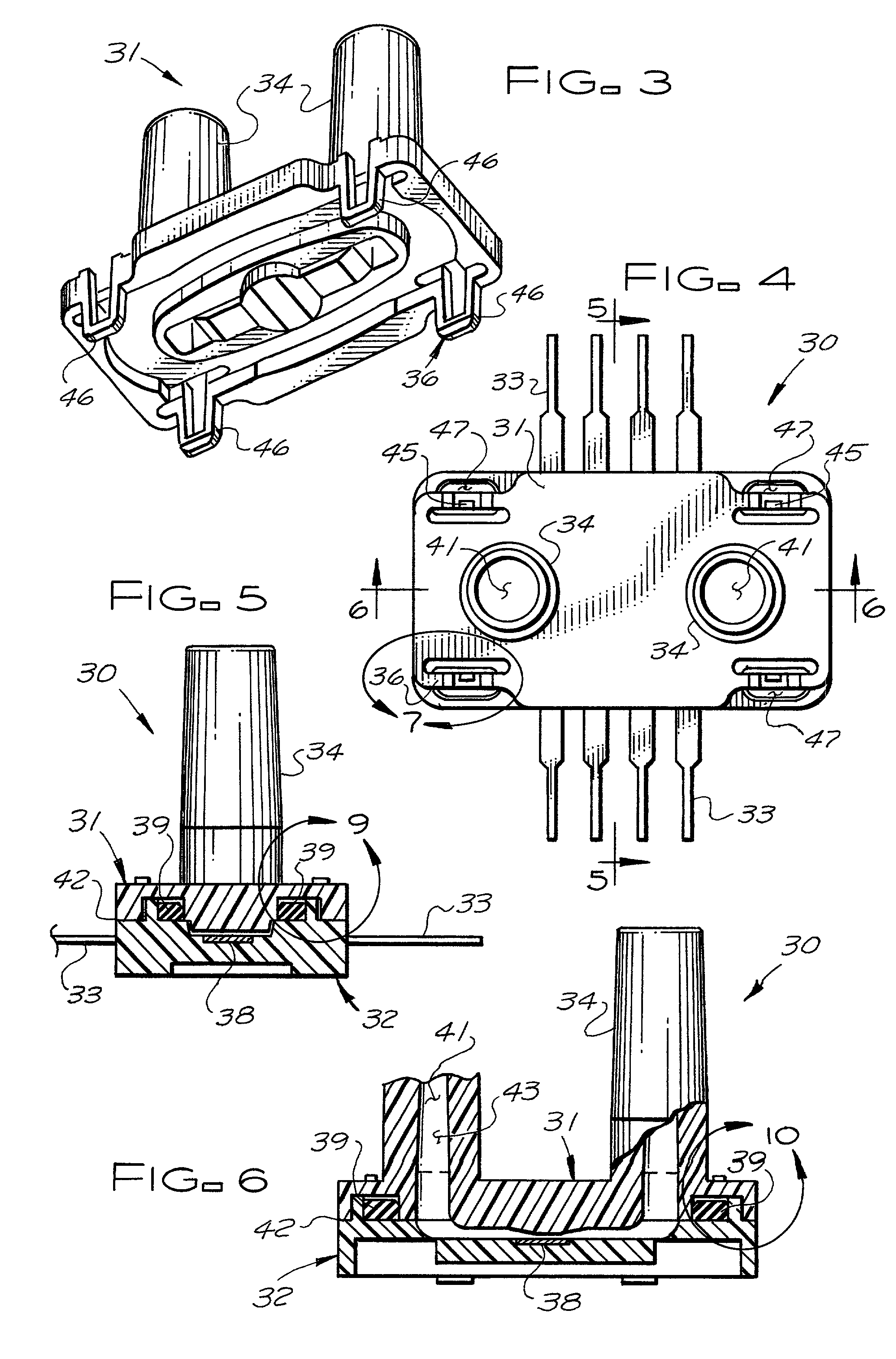
A system for sensing or measuring the motion of a fluid such as air. The system typically has a two-part plastic body containing an internal flow passage. The parts of the body may snap together or attach with an adhesive. A transducer or an electronic sensor is typically located within the flow passage, which may measure mass flow rate and may have two resistive thermal devices (RTDs) located on either side of a heat source. The body may have two elongated port tubes configured to attach to tubing. The port tubes may contain venturis, and may be substantially straight and substantially parallel, forming a U shape. A metal lead frame may be provided in electrical communication with the sensor. The lead frame may be integrally molded within the body, and may have a lower coefficient of thermal expansion than the body. The internal flow passage and the sensor may be substantially symmetrical and measure the flow rate of the fluid substantially equally in either flow direction. The system may be configured for surface mounting or for through-hole mounting, and may be a dual in-line type.

Description

[0001] 1. Field of the Invention[0002] This invention relates generally to systems and devices for sensing or measuring the motion of fluids and producing an electrical signal indicative of such motion.[0003] 2. Description of the Related Art[0004] There are many situations where it is necessary or desirable to sense or measure the velocity, pressure, or flow rate of a fluid. Such situations include fluids that are both liquids and gasses and include both internal and external flow. For example, such systems or devices may be used to measure the air-speed of an aircraft, the water flow rate in a canal, pipeline, or river, the air flow rate into an internal combustion engine, or the flow rate through a ventilation duct in a heating, ventilating, and air-conditioning (HVAC) system of an office building. In many such applications, such as where electronic controls are used, it is necessary or desirable for such measuring devices to provide an electronic output that can be displayed on ...

Claims


Application Information

Patent Timeline
IPC IPC(8): G01F15/14G01F1/684G01L19/14
CPCG01F1/6845G01F1/6842
Inventor GEHMAN, RICHARD WILLIAMBLUMHOFF, CHRISTOPHER MICHAELSPELDRICH, JAMIE WANDLER
Owner HONEYWELL INT INC
Why Eureka
Try Eureka