
Valve timing control device

a timing control and valve technology, applied in valve arrangements, machines/engines, mechanical equipment, etc., can solve the problems of difficult to prevent the occurrence of beat noise, repeating beat noise, and remaining air in the spective hydraulic chamber

Inactive Publication Date: 2002-06-27
MITSUBISHI ELECTRIC CORP
View PDF0 Cites 63 Cited by
  • Summary
  • Abstract
  • Description
  • Claims
  • Application Information

AI Technical Summary

Benefits of technology

[0024] With the above arrangement, it may further comprises a check valve having an advance side partitioned pressure path communicating the advance side hydraulic chamber and having a retardation side partitioned pressure path communicating the retardation side hydraulic chamber, the check valve selecting the higher pressure of the two different pressures in the advance and retardation side hydraulic chambers to supply the selected pressure to the unlocking hydraulic pressure supply path, wherein at least one of the advance side hydraulic chamber, the retardation side hydraulic chamber, the advance side partitioned pressure path and the retardation side partitioned pressure path is equipped with a purge path communicating to the atmosphere. In this way, air or air-mixed oil used in first motion of the unlocking operation on starting the engine can be discharged positively to outside. It is unnecessary to devote all pressure produced in the first motion to the unlocking operation. Therefore, it is possible to unlock the locking relation after the applied hydraulic pressure reaches a level of allowing the control of the valve timing control device and to prevent the occurrence of the beat noise (abnormal noise) with reliability.
[0025] With the above arrangement, the purge path may be connected to a backward pressurized section in the accommodation hole, the backward pressurized section functioning as a backward pressurized chamber for the locking member. In this way, a hydraulic pressure produced due to air-mixed oil, which is supplied to the backward pressurized section in the accommodation hole by way of the purge path, competes against an unlocking hydraulic pressure supplied to the engagement hole by way of the unlocking hydraulic pressure supply path. Therefore, it is possible to delay the unlocking operation and accordingly prevent the occurrence of the beat noise (abnormal noise) with reliability.
[0026] With the above arrangement, a drain path communicating between the purge path and the atmosphere may be connected to the backward pressurized section in the accommodation hole, the backward pressurized section functioning as a backward pressurized chamber for the locking member. In this way, it is possible to discharge quickly the air-mixed oil due to the drain path with the locking relation being unlocked.

Problems solved by technology

Therefore, the beat noise occurs due to the repetition.
It results in remaining air in there spective hydraulic chambers and pipes such as oil paths.
Since the second rotor therefor attaches repeatedly to or detaches from the first rotor 1, it is difficult to prevent the occurrence of the beat noise (abnormal noise) due to the repetition.
Therefore, there is a possibility that the locking relation of the tier-equipped pin is unlocked before the hydraulic pressure adequately rises and the conventional device cannot solve the problems above.
Therefore, when the application of the advance side hydraulic pressure is switched to the application of the retardation side hydraulic pressure, the hydraulic pressure does not exert adequately on the tier-equipped pin.
Any devices disclosed in the gazettes above are predicated on using the tier-equipped pin and it is difficult to use a straight pin usable in the conventional valve timing control device shown in FIG. 1 to FIG. 5.
In this way, however a hydraulic pressure, which is supplied to either of the retardation side hydraulic chamber and the advance side hydraulic chamber, rises on starting the engine, the locking relation of both rotors cannot be unlocked due to the risen hydraulic pressure.

Method used


Image

  • Valve timing control device
  • Valve timing control device
  • Valve timing control device

Examples


embodiment 1

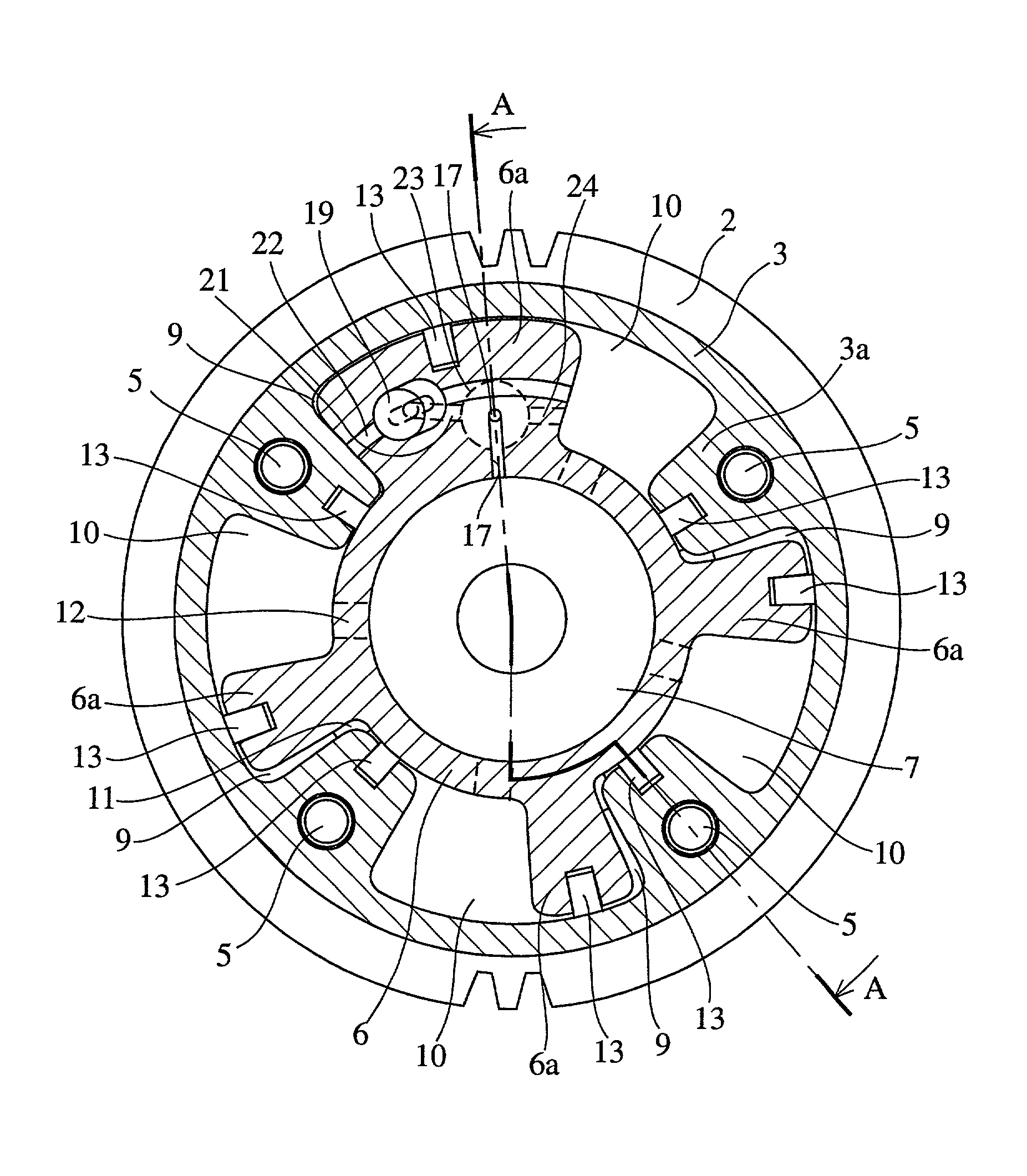
[0063] FIG. 6 is a lateral cross sectional view of an internal construction of a valve timing control device as embodiment 1 according to the present invention. FIG. 7 is a longitudinal cross sectional view taken along lines A-A of FIG. 6. FIG. 8 is an enlarged perspective view of a locking / unlocking mechanism of the valve timing control device shown in FIG. 6 and FIG. 7. FIG. 9A and FIG. 9B are longitudinal cross sectional views of an operation of the locking / unlocking mechanism of the valve timing control device shown in FIG. 6 to FIG. 8, FIG. 9A shows a locked state and FIG. 9B shows an unlocked state. FIG. 10 is a graph of a relationship between an operational stroke of a locking member of the locking mechanism of the valve timing control device shown in FIG. 6 to FIG. 9B and a hydraulic pressure exerted on the locking mechanism. Components of the embodiment 1 common to those of the conventional valve timing control device shown in FIG. 1 to FIG. 5 are denoted by the same refere...

embodiment 2

[0087] FIG. 11 is a perspective view of an important part of a locking / unlocking mechanism of a valve timing control device as embodiment 2 according to the present invention. FIG. 12A and FIG. 12B are longitudinal cross sectional views of an operation of the locking / unlocking mechanism of the valve timing control device shown in FIG. 11, FIG. 12A shows a locked state and FIG. 12B shows an unlocked state. FIG. 13 is a graph of a relation ship between an operational stroke of a locking member of the locking mechanism of the valve timing control device illustrated in FIG. 11 to FIG. 12B and a hydraulic pressure exerted on the locking member. Components of the embodiment 2 common to those of the conventional valve timing control device shown in FIG. 1 to FIG. 5 or those of the embodiment 1 are denoted by the same reference numerals and further description will be omitted.

[0088] The embodiment 2 is characterized in that a locking pin 25 defined as the tier-equipped pin is used, whereas ...

embodiment 3

[0103] FIG. 14 is a lateral cross sectional view of an internal construction of a valve timing control device as embodiment 3 according to the present invention. FIG. 15 is a perspective view of an important part of a locking / unlocking mechanism of the valve timing control device shown in FIG. 14. FIG. 16A and FIG. 16B are longitudinal cross sectional views of an operation of the locking / unlocking mechanism of the valve timing control device shown in FIG. 14 and FIG. 15, FIG. 16A shows a locked state and FIG. 16B shows an unlocked state. Components of the embodiment 3 common to those of the conventional valve timing control device shown in FIG. 1 to FIG. 5 or those of the embodiment 1 are denoted by the same reference numerals and further description will be omitted.

[0104] With the embodiment 3, a third unlocking hydraulic pressure supply path 28 is disposed at the vane 6a of the rotor 6 and a fourth unlocking hydraulic pressure supply paths 29 is disposed at the sprocket 2, instead...


PUM


Abstract

A valve timing control device includes a purge path communicating between a hydraulic chamber allowing the entry of hydraulic pressure on starting an engine and a backward pressurized section in an accommodation hole. When the hydraulic chamber allowing the entry of hydraulic pressure on starting the engine is the retardation side hydraulic chamber, a hydraulic pressure derived from an oil pump is supplied to the retardation side hydraulic chamber on starting the engine. On the way, air-mixed oil is discharged to outside of the device by way of a purge path, a backward pressurized section in the accommodation hole and the discharge hole. When the air is discharged, a residual pressure is produced in the backward pressurized section due to oil supplied thereto. The residual pressure results in the increase of an unlocking hydraulic pressure to prevent a locking member from being unlocked. When the application of a retardation side hydraulic pressure is switched to that of an advance side hydraulic pressure, the pressure presses a front end of a locking member against only a biasing force of a biasing means to unlock a locking relation. The valve timing control device allows the use of any kinds of locking pins, and prevents the occurrence of beat noise (abnormal noise) when air-mixed oil unlocks a locking relation on starting the engine.

Description

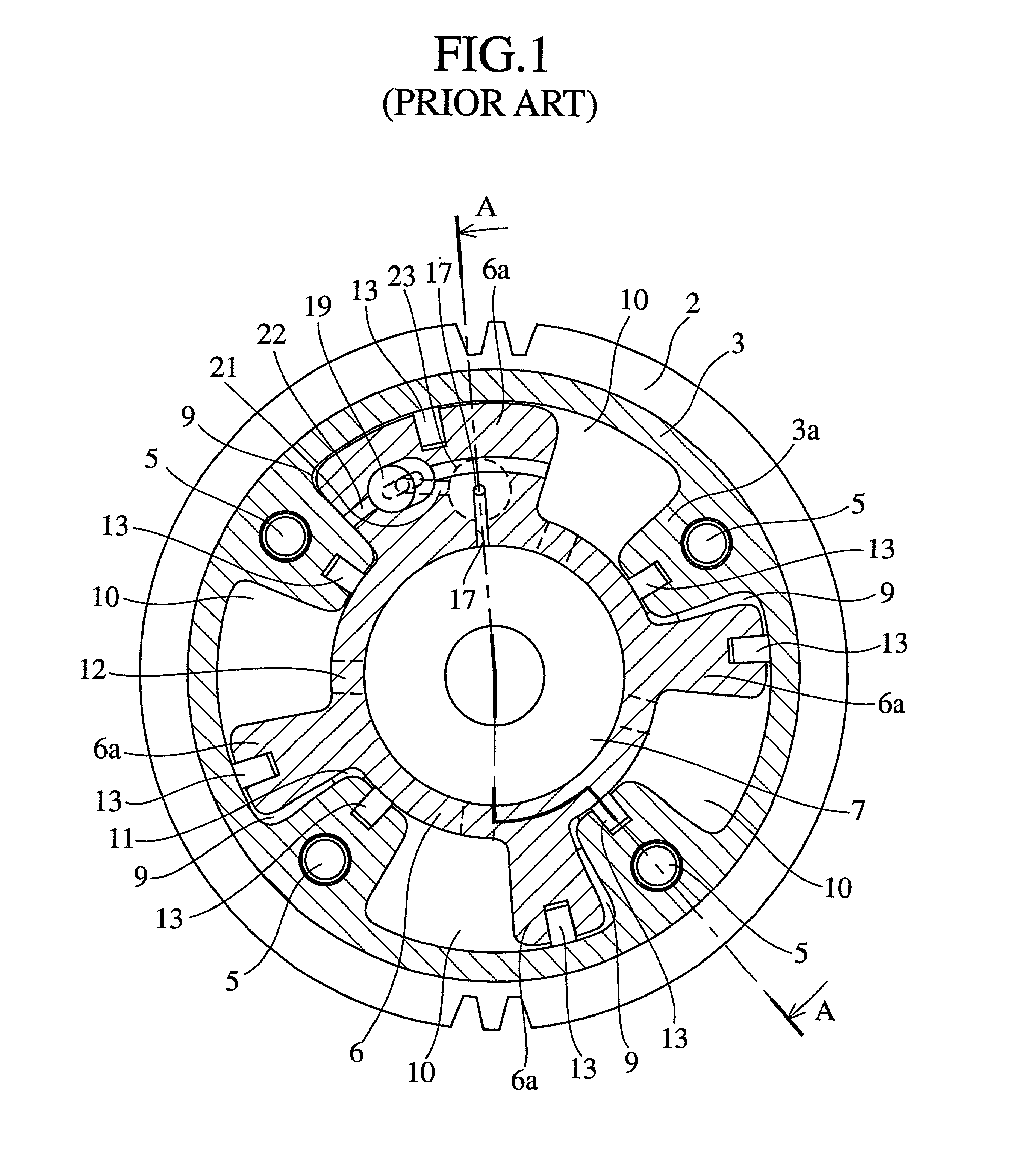
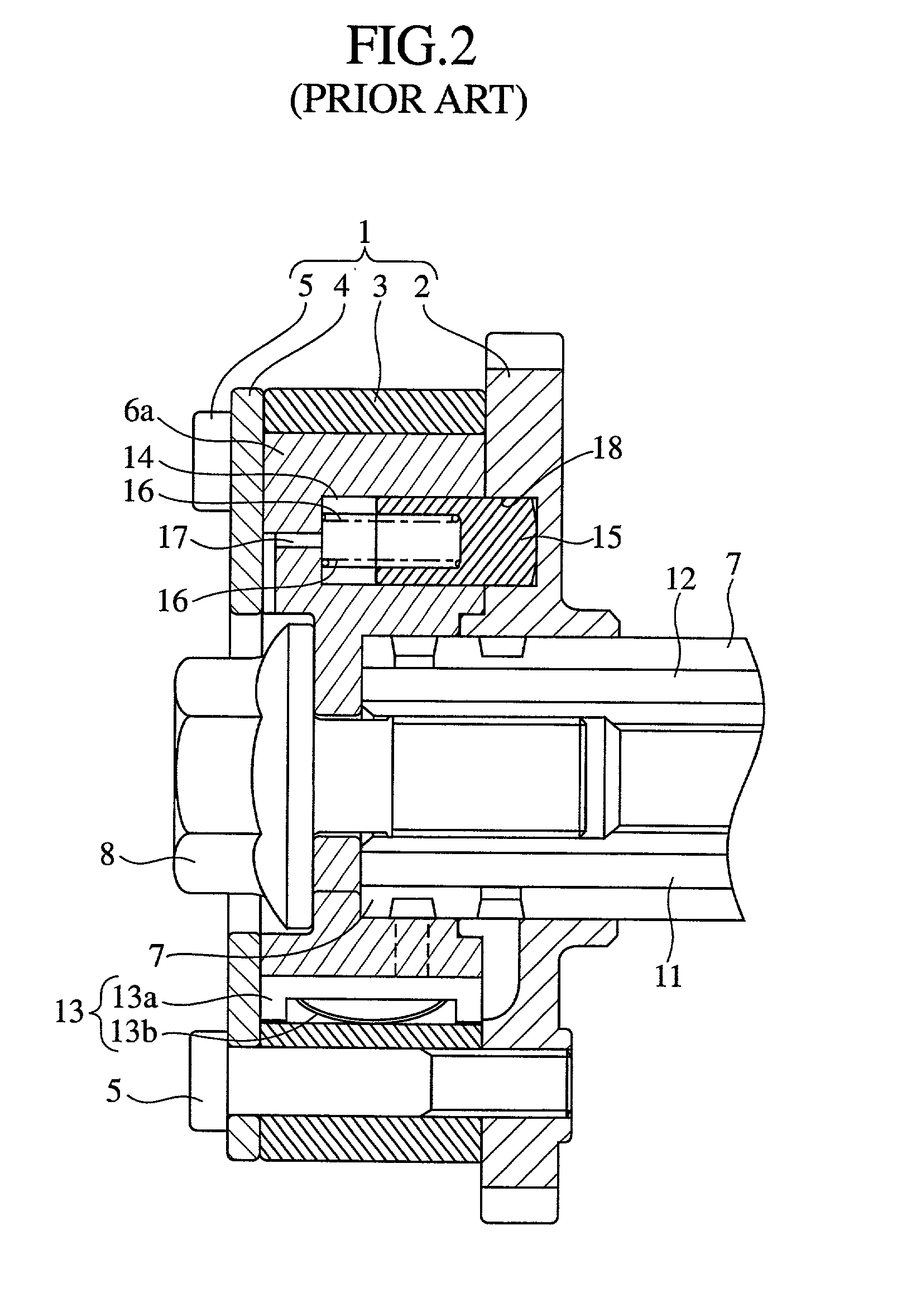
CROSS REFERENCE[0001] This application is a continuation-in-part of Serial No. 09 / 891,172, filed Jun. 26, 2001.[0002] 1 Field of the Invention[0003] The present invention relates to a valve timing control device altering timing for the closing and opening of an exhaust valve or intake valve of an internal-combustion engine (hereafter, referred as an engine) with reference to any operating conditions.[0004] 2. Description of the Prior Art[0005] Conventional valve timing control devices shown in FIG. 1 to FIG. 5 for example are known. FIG. 1 is a lateral cross sectional view of an internal construction of a conventional vane-equipped valve timing control device. FIG. 2 is a longitudinal cross sectional view taken along lines A-A of FIG. 1. FIG. 3 is a longitudinal cross sectional view of a conventional locking / unlocking mechanism shown in FIG. 2. FIG. 4 is an enlarged perspective view of an important part of a locking / unlocking mechanism of the conventional valve timing control device...

Claims


Application Information

Patent Timeline
Patent Type & Authority Applications(United States)
IPC IPC(8): F01L1/344
CPCF01L1/344F01L1/3442F01L2001/34469F01L2001/34473F01L2001/34479F01L2001/34466
Inventor FUKUHARA, KATSUYUKIKINUGAWA, HIROYUKIYAMAUCHI, MAKOTO
Owner MITSUBISHI ELECTRIC CORP
Learn More