

Method for estimating and controlling flow pattern of molten steel in continuous casting and apparatus therefor
- Summary
- Abstract
- Description
- Claims
- Application Information
AI Technical Summary
Benefits of technology
Problems solved by technology
Method used
Image

Examples
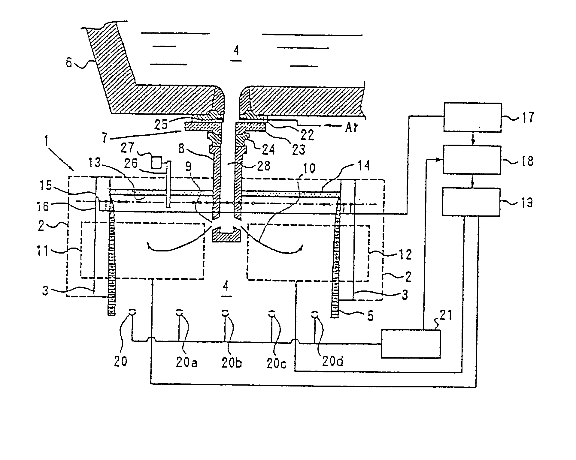
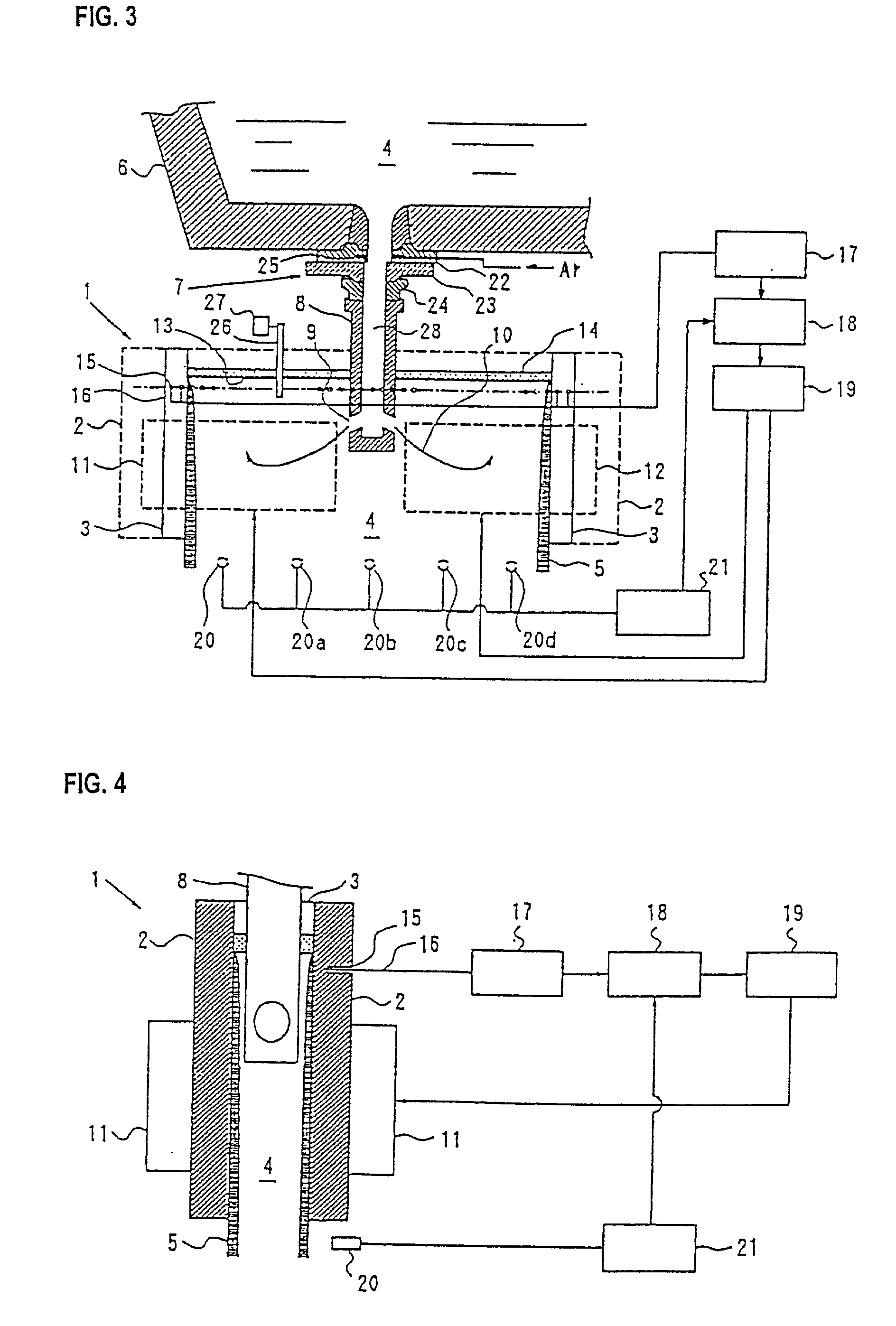
embodiment 1
[0177] Embodiment 1
[0178] (Method for Controlling the Flow Pattern of Molten Steel)
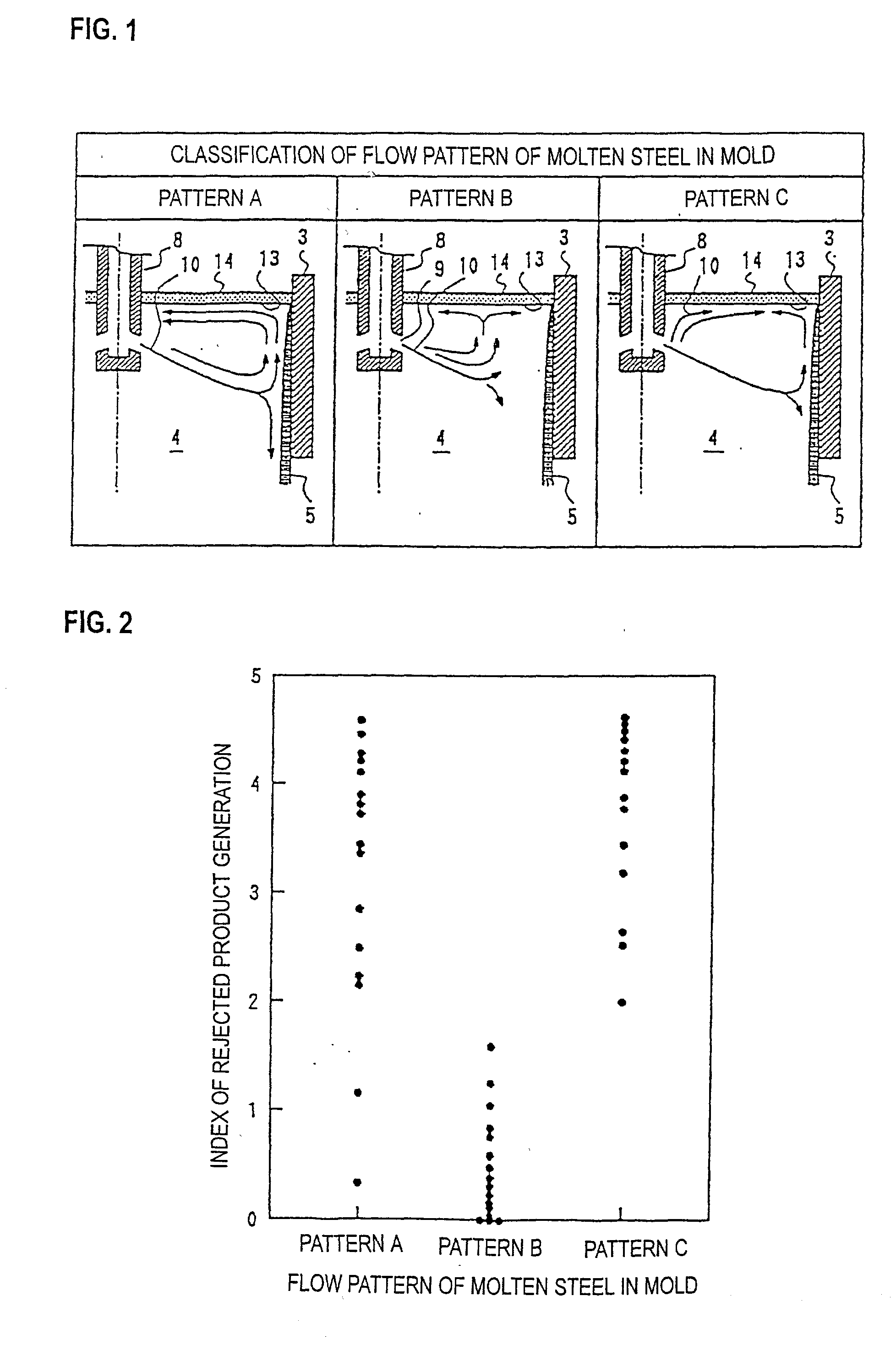
[0179] Flow pattern of molten steel in a mold varies in complex modes caused from the influences of ascending Ar bubbles and of applied magnetic field even in a symmetrical flow in right half width and in left half width in the mold to the immersion nozzle without deflection. The flow patterns are largely classified to three patterns: Pattern A, Pattern B, and Pattern C, which are illustrated in FIG. 1. In the figure, the reference number 3 designates the shorter side of the mold, 4 designates the molten steel, 5 designates the solidified shell, 8 designates the immersion nozzle, 9 designates the injection hole, 10 designates the injected flow, 13 designates the meniscus, and 14 designates the mold powder.
[0180] According to the Pattern A, the injected flow 10 coming from the immersion nozzle 8 reaches to and collides against the solidified shell 5 on shorter side 3 of the mold, then separates in two ...
embodiment 2
[0214] Embodiment 2
[0215] (Method for Estimating Flow Pattern of Molten Steel and Apparatus Therefor)
[0216] The inventors of the present invention investigated the positions for mounting the temperature measurement elements buried in the mold copper plate to accurately detect the flow of molten steel even when complex flow of molten steel exits in the vicinity of the meniscus.
[0217] First, the intervals of temperature measurement elements in width direction of the mold were investigated. As of the complex flows of molten steel at near the meniscus, the profile of molten steel flow speed in the vicinity of meniscus along the width direction of the mold is a particularly important variable in view of quality control. To this point, the continuous casting machine which is applied in the embodiments described later was applied. An end of a refractory rod was immersed in the meniscus. A flow meter for the molten steel was used to determine the flow speed of the molten steel by measuring ...
embodiment 3
[0275] Embodiment 3
[0276] (Method for Judging Surface Defect on Continuously Cast Slab)
[0277] The inventors of the present invention conducted measurements on a commercial facility, model experiments, and numerical analyses to investigate the flow state of molten steel in the mold under various casting conditions, and the temperature profile on the mold copper plate in the mold width direction. FIG. 37 shows schematic illustration of comparison between the flow state of molten steel in the mold and the temperature of mold copper plate. In the figure, the reference number 206 designates the copper plate on shorter side of the mold, 211 designates the meniscus, 215 designates the immersion nozzle, 216 designates the injection hole, 217 designates the injected flow, and the injected flow 217 indicates the flow direction by arrow mark.
[0278] In the Pattern 0, no governing flow exists, and a mild flow appears over the whole width of the mold, thus the measured values on the temperature m...
PUM
| Property | Measurement | Unit |
|---|---|---|
| Length | aaaaa | aaaaa |
| Time | aaaaa | aaaaa |
| Angle | aaaaa | aaaaa |
Abstract
Description
Claims
Application Information