
Stator winding and coil lead termination method and apparatus

Inactive Publication Date: 2002-06-27
GLOBE PRODS
View PDF0 Cites 16 Cited by
  • Summary
  • Abstract
  • Description
  • Claims
  • Application Information

AI Technical Summary

Benefits of technology

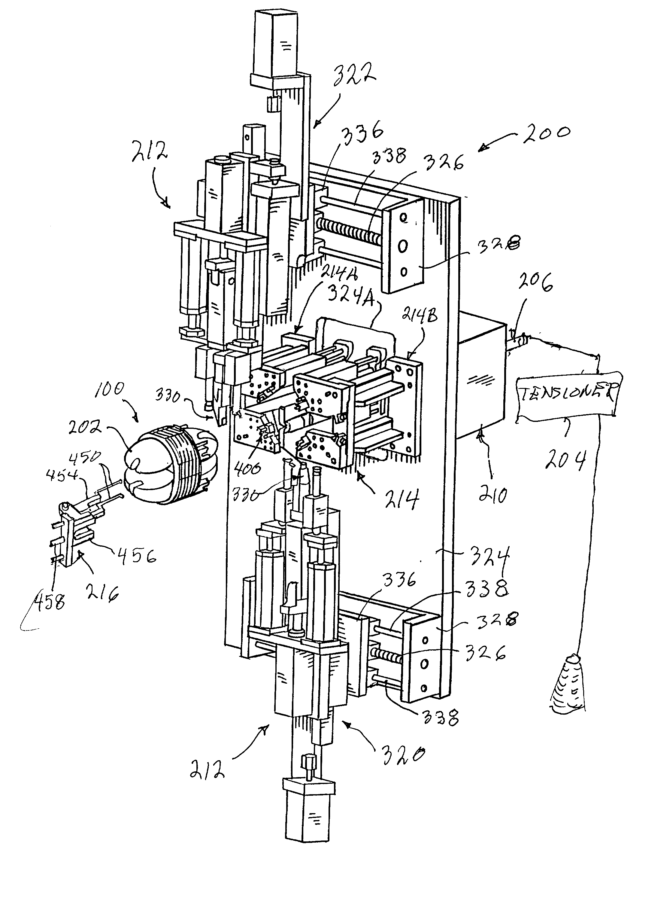
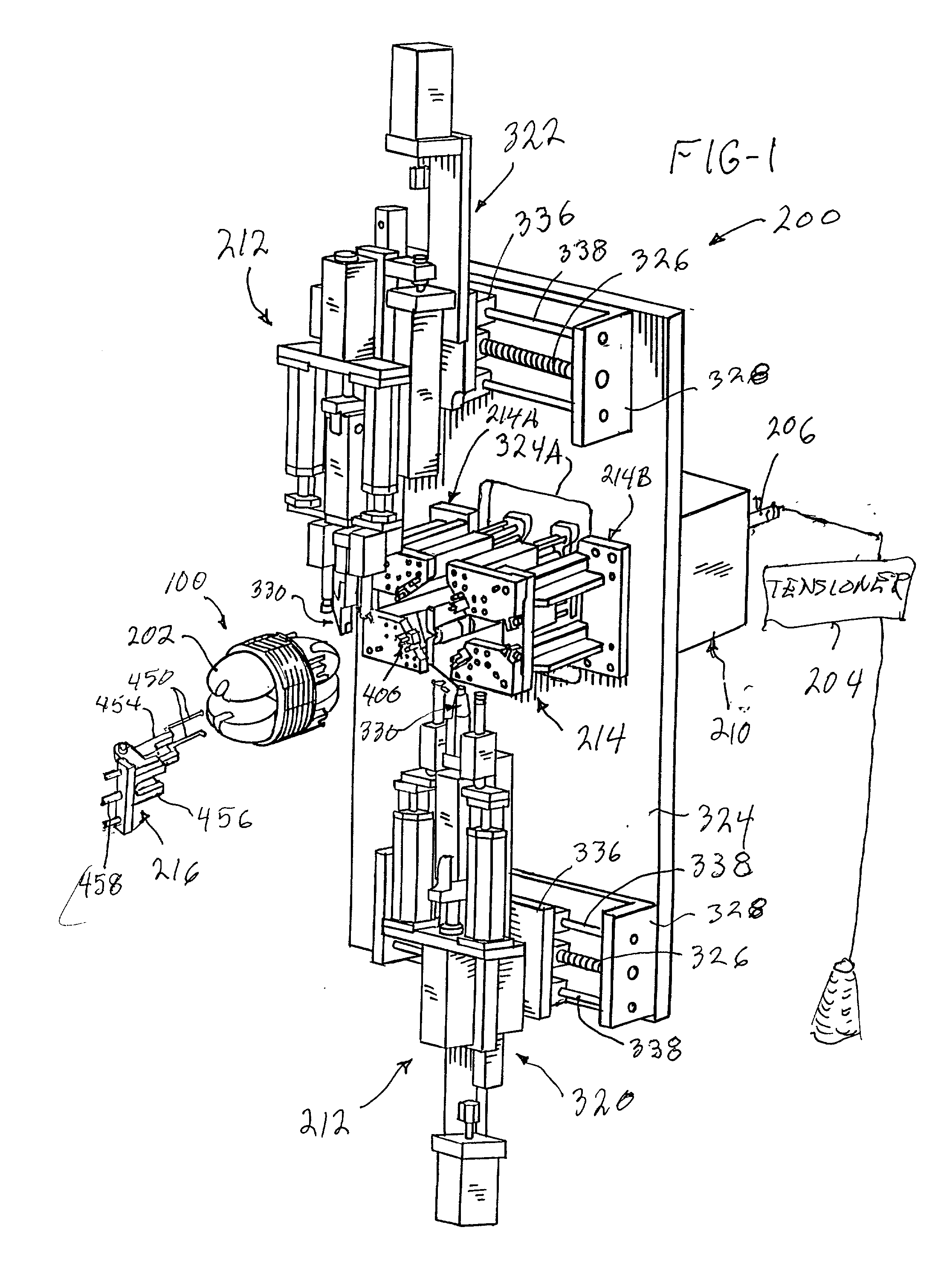
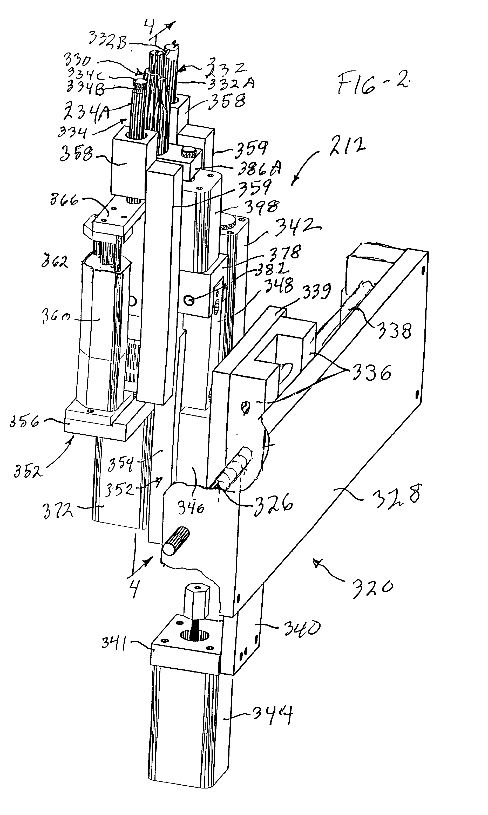
[0028] Another object of this invention is to provide an improved stator coil lead terminating method and apparatus which is capable of complex manipulations of stator coil lead wires at a winding station.

Problems solved by technology

Recent developments in stator technology have resulted in demands for stator winding methods which cannot be met by known stator winding machines.
There are no prior machines known that are capable of winding and terminating such stators entirely automatically.

Method used


Image

  • Stator winding and coil lead termination method and apparatus
  • Stator winding and coil lead termination method and apparatus
  • Stator winding and coil lead termination method and apparatus

Examples


Embodiment Construction

[0052] Stators and Stator Winding Patterns

[0053] Referring to FIGS. 15 through 17, this invention is illustrated herein for winding a 2-pole electric motor stator 100 comprising a laminated iron core 102 formed to include a central, armature-receiving bore 104 and a pair of diametrically opposed pole pieces, namely a first, lower pole piece 106 and a second, upper pole piece 108. The pole pieces 106 and 108 are bounded by stator coil-receiving slots 110 in which are located insulating linings 112 known as "cell papers." Stator coils C1 and C2 are wound into the coil-receiving slots 110.

[0054] A so-called "end fiber" or plastic terminal board 114 is located at one end of the stack of iron laminations that form the laminated core 102. The end of the stator 100 which has the terminal board 114 is, for purposes of this description, considered to be the rear of the stator, this being the end of the stator farthest from an observer standing in front of the winding machine. The opposite en...


PUM

PropertyMeasurementUnit
Angleaaaaaaaaaa
Forceaaaaaaaaaa
Bending strengthaaaaaaaaaa

Abstract

The reciprocating and oscillating winding spindle of a stator winding machine is rotatable through 180.degree. to enable a stator winding and lead terminating method and apparatus for automatically winding a 2-pole stator having two pole pieces each with a coil wire wound from the same, single strand of wire. A cross-over wire segment between the two stator coils extends through the bore of the stator and is trapped against an inside wall of the stator by a cross-over wire retaining member. A stator coil lead terminating apparatus is capable of complex manipulations of stator coil lead wires at a winding station. Stator coil lead wires can be looped about wire guide posts on a stator core in the course of forming coil lead terminations, and the posts can be protected against bending or breaking by looping pins that partly receive the posts.

Description

CROSS REFERENCE TO RELATED APPLICATIONS[0001] This application claims the benefit of U.S. Provisional Application No. 60 / 196,836, filed Apr. 13, 2000.FIELD OF THE INVENTION[0002] This invention relates to a stator winding and coil lead termination method and apparatus. The invention is intended primarily for use in the manufacture of 2-pole stators for dynamoelectric machines, such as motors, but may have application to the manufacture of other devices.INCORPORATION BY REFERENCE[0003] The disclosures of the following patents are hereby incorporated by reference herein.[0004] 1. U.S. Pat. No. 4,074,418 to Pearsall[0005] 2. U.S. Pat. No. 5,186,405 to Beakes et al.[0006] 3. U.S. Pat. No. 5,586,384 to Newman[0007] 4. U.S. Pat. No. 5,413,403 to Beakes et al.BACKGROUND OF THE INVENTION[0008] Many electric motor stators are configured to include a non-conductive terminal board mounted to an end face of the stator core, which terminal board carries electrically conductive terminals to which...

Claims


Application Information

Patent Timeline
IPC IPC(8): H02K15/00H02K15/095
CPCH02K15/0056Y10T29/49009H02K15/095H02K15/0075H02K15/0068
Inventor DOLGAS, PATRICK A.BRADFUTE, JOHN W.BUSSERT, DAMON E.CLEMENZ, GARY E.STATON, LARRY E.WILLIAMS, ARLIE D.
Owner GLOBE PRODS
Learn More