Energy pathway arrangement
- Summary
- Abstract
- Description
- Claims
- Application Information
AI Technical Summary
Problems solved by technology
Method used
Image
Examples
embodiment 6000
[0130] However when conductive isolation of the shielding structure is maintained, a path of least impedance created with coupling to a non-complementary energy pathway of the circuit systems involved will dynamically create a low impedance energy pathway common to energies of the at least two isolated circuit systems as they are operable and arranged for operations relative to the other, such as for straight stacking like embodiment 6000, one above the other relative to at least a respective positioning that reveals such a stacked or adjacent arrangement between the plurality of shield electrodes.
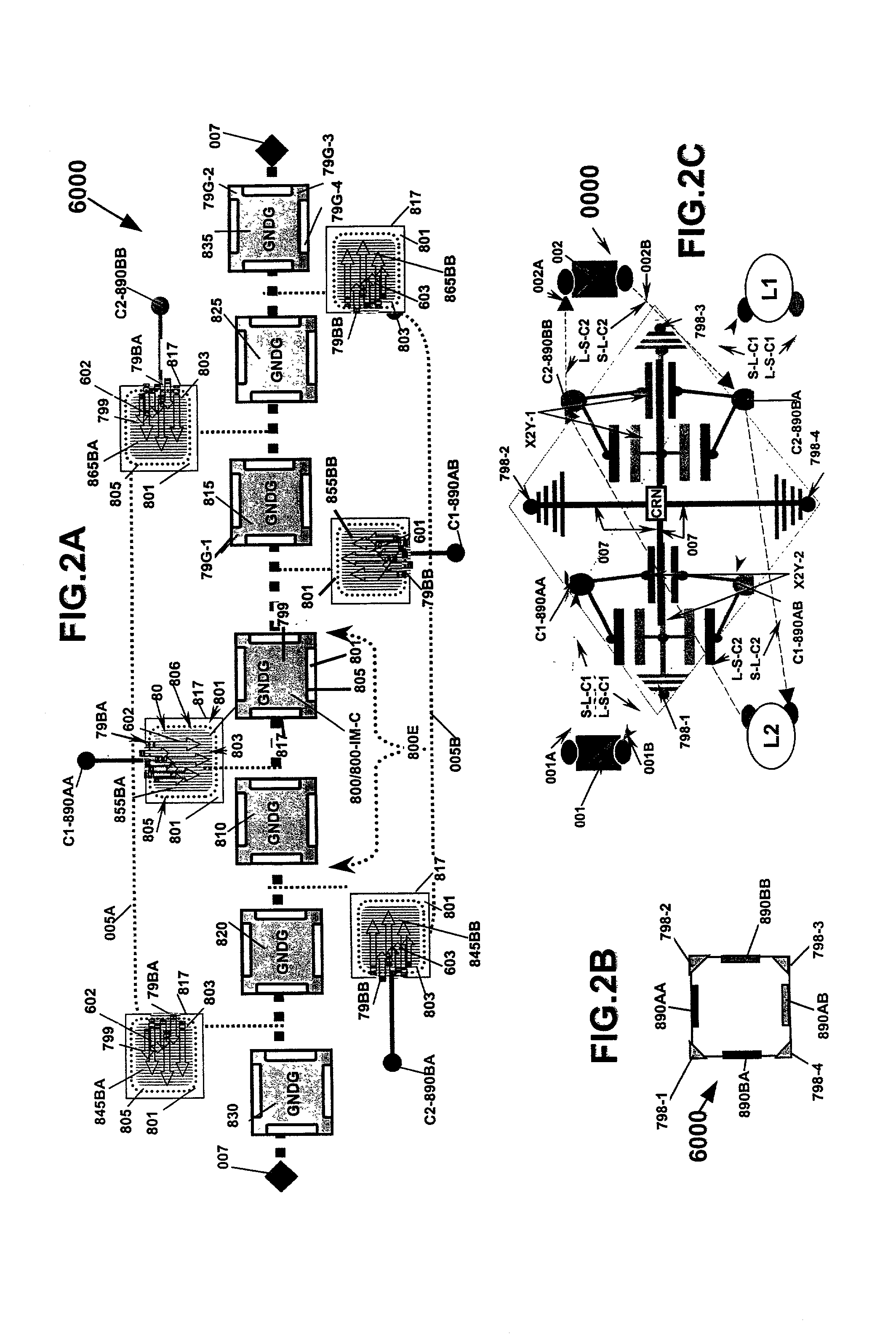
[0131] Referring now to FIGS. 2A-2B, an embodiment of an energy conditioner 6000. Energy conditioner 6000, among others is shown in FIG. 2A as an exploded view showing the individual electrode layering formed or disposed on layers of material 801, as discussed above. A predetermined embodiment structure of FIG. 2A among others is a predetermined shielding, electrode arrangement comprising ...
embodiment 1000
[0235] Referring to FIG. 7A and FIG. 7B, one discrete embodiment 1000 of an energy-conditioning component utilizing all bypass electrode sections similar to by pass sections of FIGS. 5C-5D is shown as a typical minimum-layered sequence for coupling to multiple separate circuits.
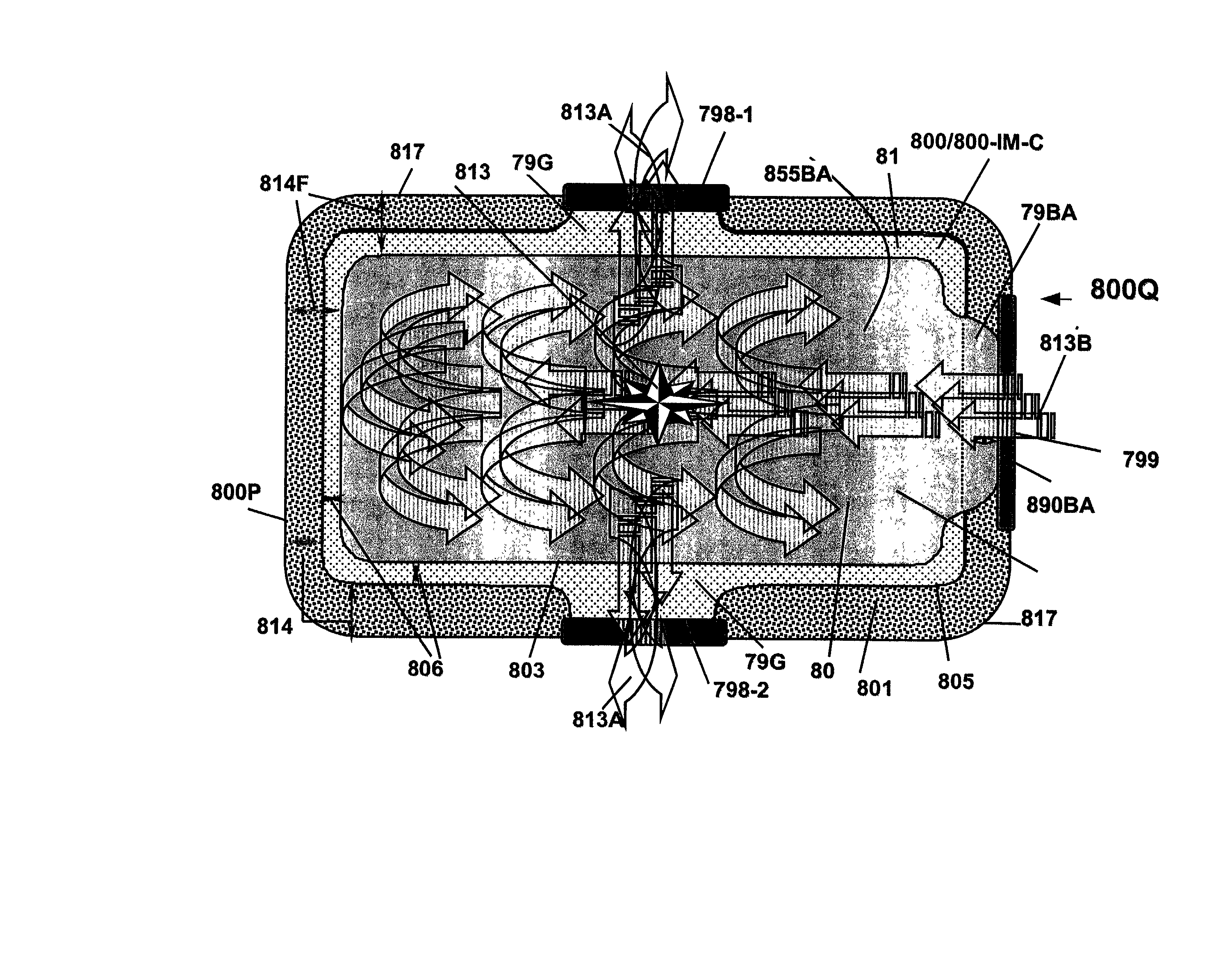
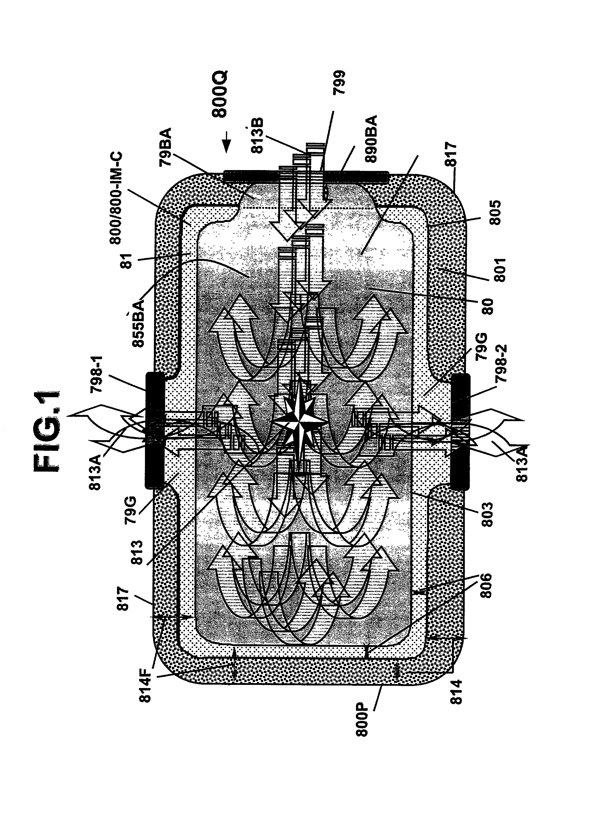
[0236] Complementary pairings of co-planar bypass main-body electrode sections 80 in arranged layerings are shown arranged within a plurality of larger sized, shaped electrodes 800, 810, 815. Each shaped main-body electrode 81 of electrodes 800, 810, 815 is formed on as a larger electrode on material 801 portion 800P, 810P, 815P. Each co-planar electrode layering comprises four equally sized main-body electrode portion 80s having at least one extension portion 79-"X", respectively.
[0237] Each co-planar electrode layering is arranged between at least two shaped main-body electrode portion 81s of shielding electrodes from the plurality of shielding electrodes comprising at least electrodes 800, 810, 815. Each s...
embodiment 1200
[0239] Referring now to FIG. 7B, and FIG. 5A and FIG. 5B, one discrete embodiment 1200 of an energy-conditioning component could be utilizing layerings of either FIGS. 5A-5B or FIG. 7A as is shown as a minimum outer electrode sequence for coupling to multiple, separate circuits.
[0240] A view of the energy-conditioning component 1200 is shown utilizing minimum layered sequence of FIG. 7A. Each shaped portion electrode 855BA1, 855BA2, 855BA3 and 855BA4 of the first co-planar layering and each shaped portion electrode 855BB1, 855BB2, 855BB3 and 855BB4 of the second co-planar layering has at least one extension that is each is coupled to its own outer electrode 890A-894A, while for the inner extension portions, each is coupled to its respective the inner electrodes 890B-894B in the minimum layered sequence of FIG. 7A.
[0241] Each the respective outer side, extension portion is conductively coupled to an outer electrode portion positioned along the outer perimeter circumference edge 817-O...
PUM
 Abstract
Description
Claims
Application Information
 - R&D
- Intellectual Property
- Life Sciences
- Materials
- Tech Scout
- Unparalleled Data Quality
- Higher Quality Content
- 60% Fewer Hallucinations
Browse by: Latest US Patents, China's latest patents, Technical Efficacy Thesaurus, Application Domain, Technology Topic, Popular Technical Reports.
© 2025 PatSnap. All rights reserved.Legal|Privacy policy|Modern Slavery Act Transparency Statement|Sitemap|About US| Contact US: help@patsnap.com


