Systems and methods for single magnetron sputtering

a single magnetron and sputtering technology, applied in the field of single magnetron sputtering, can solve the problems of adverse effects of the sputtering process

Active Publication Date: 2017-01-26
AES GLOBAL HLDG PTE LTD
View PDF1 Cites 27 Cited by
  • Summary
  • Abstract
  • Description
  • Claims
  • Application Information

AI Technical Summary

Benefits of technology

[0008]As previously stated, the above-described examples and implementations are for illustration purposes only. Numerous other examples, embodiments, implementations, and details of the invention are easily recognized by those of skill in the art from the following descriptions and claims.

Problems solved by technology

In use, however, the anode becomes coated with an insulating (dielectric) film, and the sputtering process is adversely affected.

Method used


Image

  • Systems and methods for single magnetron sputtering
  • Systems and methods for single magnetron sputtering
  • Systems and methods for single magnetron sputtering

Examples


Embodiment Construction

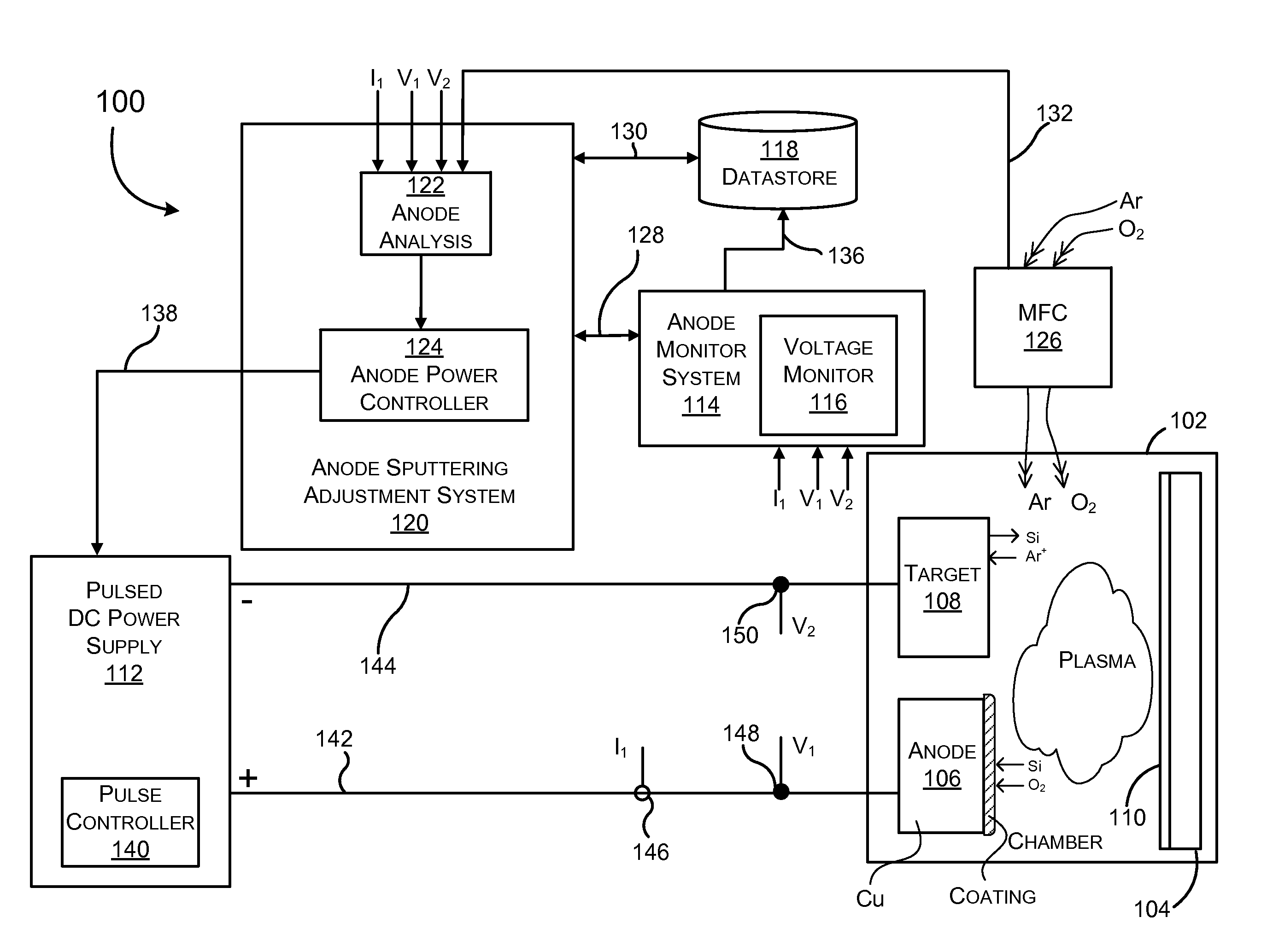
[0023]As previously mentioned in the summary of this disclosure, and broadly described, a single magnetron sputtering system may be provided in some embodiments. The system may automatically determine a health of an anode, and, responsive to determining the health of the anode, adjust an anode sputtering pulse to eject dielectric material from the anode. The system may also or alternatively provide an operator with a warning as the anode health deteriorates, and / or information about the health of the anode to enable the operator to preemptively modify the sputtering process. Methods for generating anode health data are also disclosed in this document.

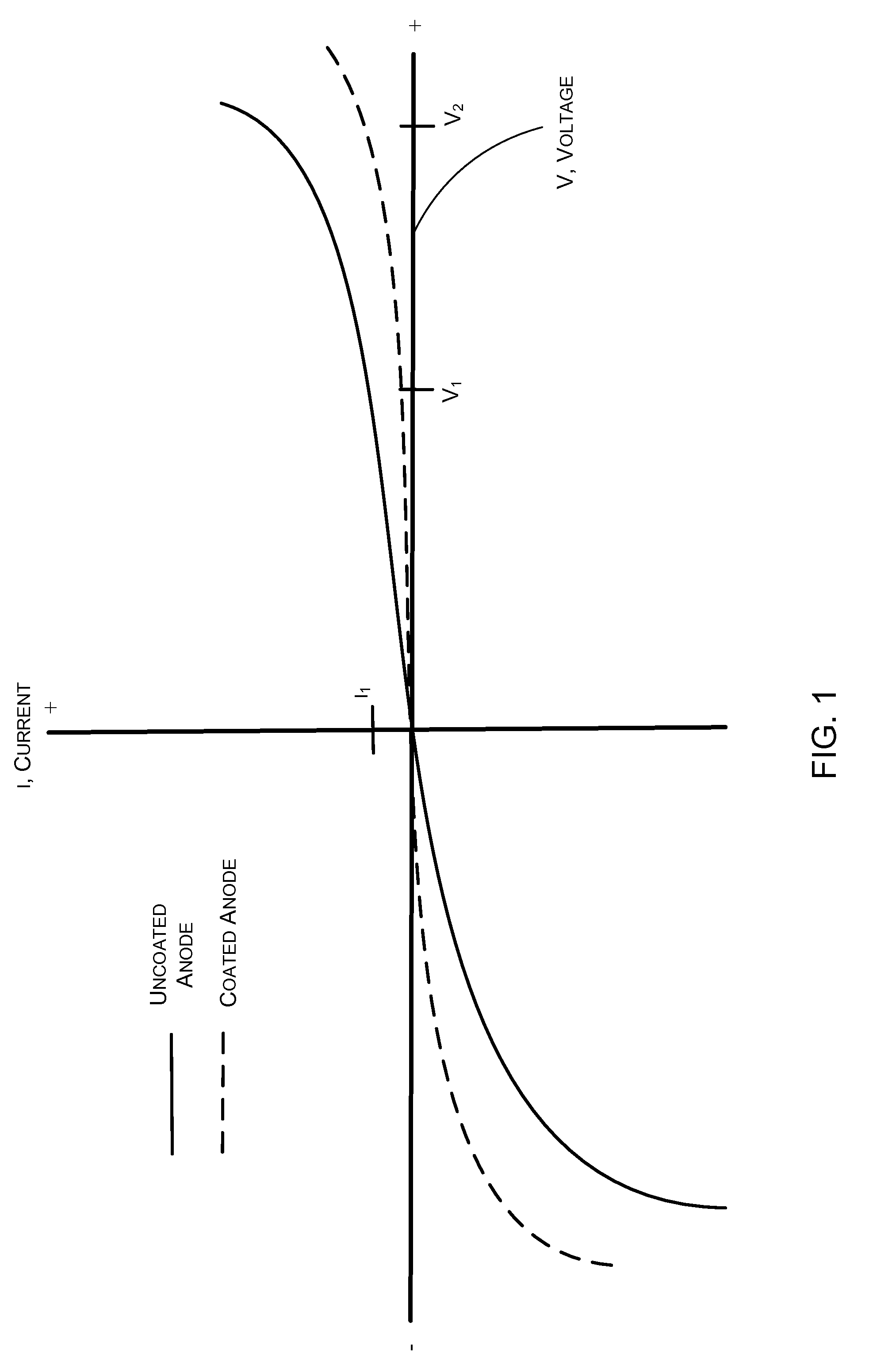
[0024]With reference to FIG. 1, it is expedient to describe the Applicant's observations as to how an anode behaves during the sputtering process. The Applicant has observed that an anode that is partially or fully coated with a dielectric material behaves differently than does a fresh or uncoated anode. Specifically, when a current I1 ...


PUM

PropertyMeasurementUnit
voltageaaaaaaaaaa
sputtering energyaaaaaaaaaa
energyaaaaaaaaaa

Abstract

A system and method for single magnetron sputtering are described. One example includes a system having a power supply, a plasma chamber enclosing a substrate, an anode, and a target for depositing a thin film material on the substrate. This example also has a datastore with uncoated anode characterization data and an anode sputtering adjustment system including an anode analysis component to generate a first health value. The first health value is indicative of whether the anode is coated with a dielectric material. This example also has an anode power controller to receive the first health value and provide an anode-energy-control signal to the pulse controller of the pulsed DC power supply to adjust a second anode sputtering energy relative to a first anode sputtering energy to eject at least a portion of the dielectric material from the anode.

Description

FIELD OF THE INVENTION[0001]The present invention relates to sputtering. In particular, but not by way of limitation, the present invention relates to systems and methods for single magnetron sputtering.BACKGROUND OF THE INVENTION[0002]Sputtering historically includes generating a magnetic field in a vacuum chamber and causing a plasma beam in the chamber to strike a sacrificial target, thereby causing the target to sputter (eject) material, which is then deposited as a thin film layer on a substrate. Sputtering sources may employ magnetrons that utilize strong electric and magnetic fields to confine charged plasma particles close to the surface of the target. An anode is generally provided to collect electrons from the plasma to maintain plasma neutrality as ions leave to bombard the target. In use, however, the anode becomes coated with an insulating (dielectric) film, and the sputtering process is adversely affected. The industry has attempted over the years to provide sputtering...

Claims


Application Information

Patent Timeline
Patent Type & Authority Applications(United States)
IPC IPC(8): C23C14/35H01J37/34
CPCC23C14/35H01J37/3476H01J37/3405C23C14/3485C23C14/3492H01J37/3438H01J37/3488
Inventor CHRISTIE, DAVIDLARSON, SKIP B.
Owner AES GLOBAL HLDG PTE LTD
Why Eureka
Try Eureka