Aerosol dispensing inhaler training device

a training device and inhaler technology, applied in the field of inhaler, can solve the problems of inhalation speed, inability to accurately measure the inhalation rate of inhalers,

Inactive Publication Date: 2002-07-11
1263152 ONTARIO
View PDF0 Cites 97 Cited by
  • Summary
  • Abstract
  • Description
  • Claims
  • Application Information

AI Technical Summary

Problems solved by technology

It is well recognized that improper inhalation technique in the use of MDI devices is a serious barrier to effective therapy.
Some patients may have difficulty in the use of conventional MDI devices especially in terms of controlling inhalation, and proper activation timing of the MDI delivery system.
For example, patients may inhale too fast, or in an erratic manner.
Another common problem is that patients may delay activation of the MDI device until after inspiration has started, and therefore, the crucial initial portion of the inspired breath does not contain medication.
After activation, patients may frequently begin their MDI inspiration breaths at improper levels of lung volume, for example, their lungs may already be relatively full of air and therefore a proper large volume of inspired air is impossible.
However, this desirable time may be functionally limited, as dictated by individual patient needs and breath holding capabilities.
Without proper MDI inhalation technique, the patient may in fact derive little or no benefit from this form of drug therapy.
One disadvantage to the above flow rate techniques, except the ultrasonics technique, is that the liquid particles present in a patient's exhaled gas can contaminate the flow rate devices to the extent that they produce inaccurate readings.
The ultrasonics technique suffers the drawback that it requires relatively expensive piezoelectric elements and complex signal analysis that limits widespread application.
In the case of teaching proper usage of a metered dose inhaler, past devices and systems have omitted teaching the proper technique for shaking the aerosol container prior to inhalation.

Method used


Image

  • Aerosol dispensing inhaler training device
  • Aerosol dispensing inhaler training device
  • Aerosol dispensing inhaler training device

Examples


second embodiment

[0058] a flow rate measurement device 300 is shown in FIGS. 7A-B where the flow rate measurement device 300 of FIGS. 6A-C is altered by adding a second magnetic element 314 that is spaced from the sensor 308 by approximately 2 mm at the rest position shown in FIG. 7A. The magnetic element 314 is attached to the vane 302 via an arm 316.

third embodiment

[0059] As shown in FIGS. 8A-8D, a flow rate measurement device 300 is a variation of the flow rate measurement device 300 of FIGS. 7A-B where the vane 302 is offset from the support 312 by approximately 1 mm at the rest position. This results in the magnetic element 310 being spaced from the sensor 308 at the rest position by approximately 1 mm. As shown in FIGS. 8B and 8C, offsetting the vane 302 allows the flow rate measurement device 300 to measure the flow rate in two directions and to determine which direction the flow is moving within the exhaust port 220. This provides the advantage of sensing the flow rate when the user exhales into the exhaust port 220.

[0060] An example of the use of a bi-directional sensor is shown in FIG. 8D where the vane 302 is used as a flow sensor in a section of a life support ventilator circuit 319. The ventilator circuit is the common descriptor for the tubing, connectors and other components that confine and direct gas from a ventilator to the pat...

fourth embodiment

[0061] a flow rate measurement device 300 is shown in FIGS. 9A-B. In this preferred embodiment, the vane 302 is oriented horizontally rather than vertically as in FIGS. 6-8 so that the free end 318 points toward the mouth piece 216 and along the flow of the gas. In this embodiment, the magnetic element 310 is attached to the top surface of the vane 302 so as to be approximately 0.375 cm from the free end 318 and approximately 0.675 cm from either of the side edges 320 of the vane 302. The sensor 308 is attached to bottom platform 322 so as to face the bottom of the vane 302. When there is no flow, the bottom surface of the vane 302 may be either adjacent to the sensor 308 or may be preloaded so that it is spaced approximately 0.6 cm from the sensor 308.

[0062] Note that several variations of the flow rate measurement devices 300 of FIGS. 6-9 are possible. For example, the sensor 308 could be attached to the vane 302 and the magnetic element 310 could be mounted on the support 312 or ...


PUM


Abstract

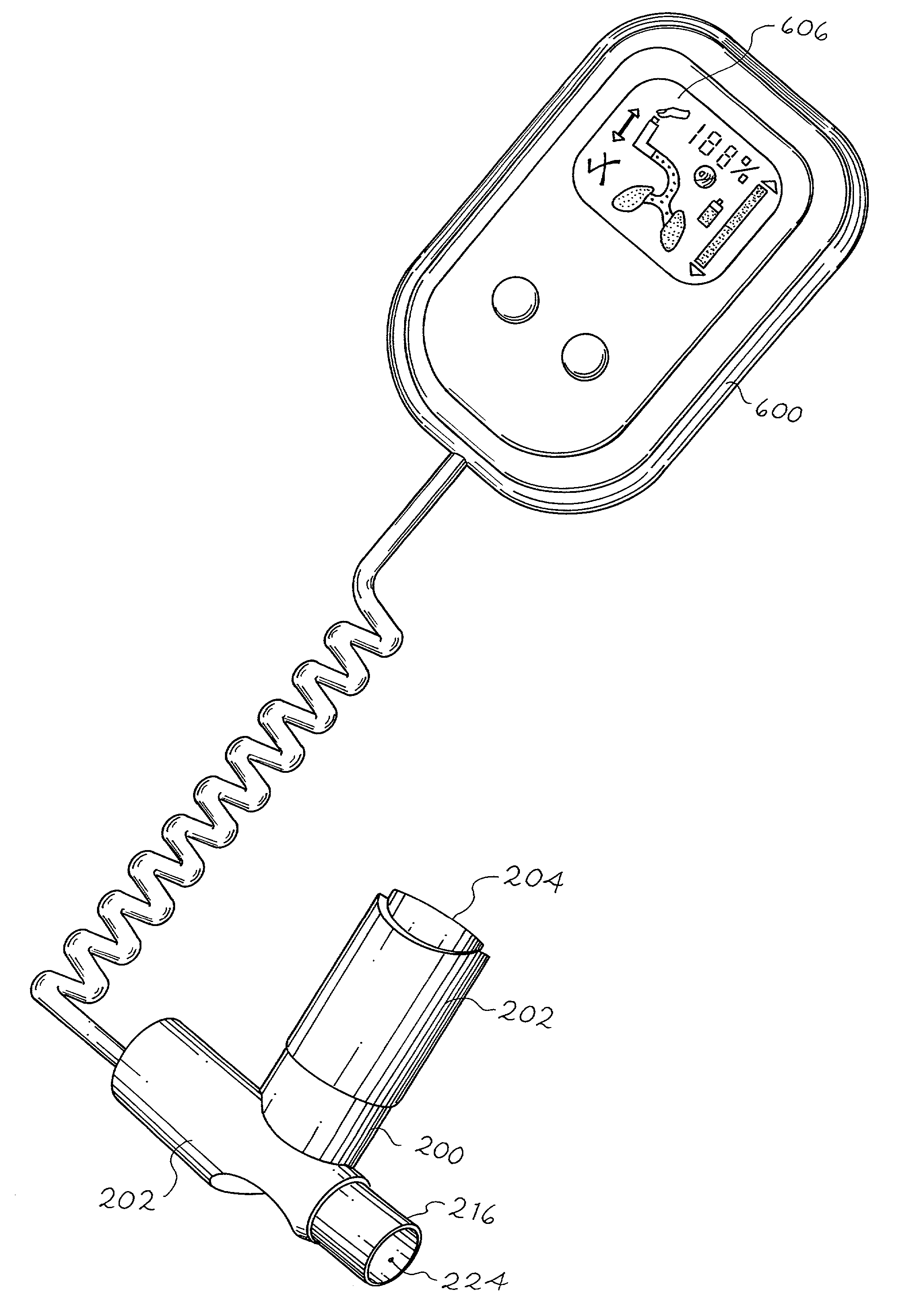
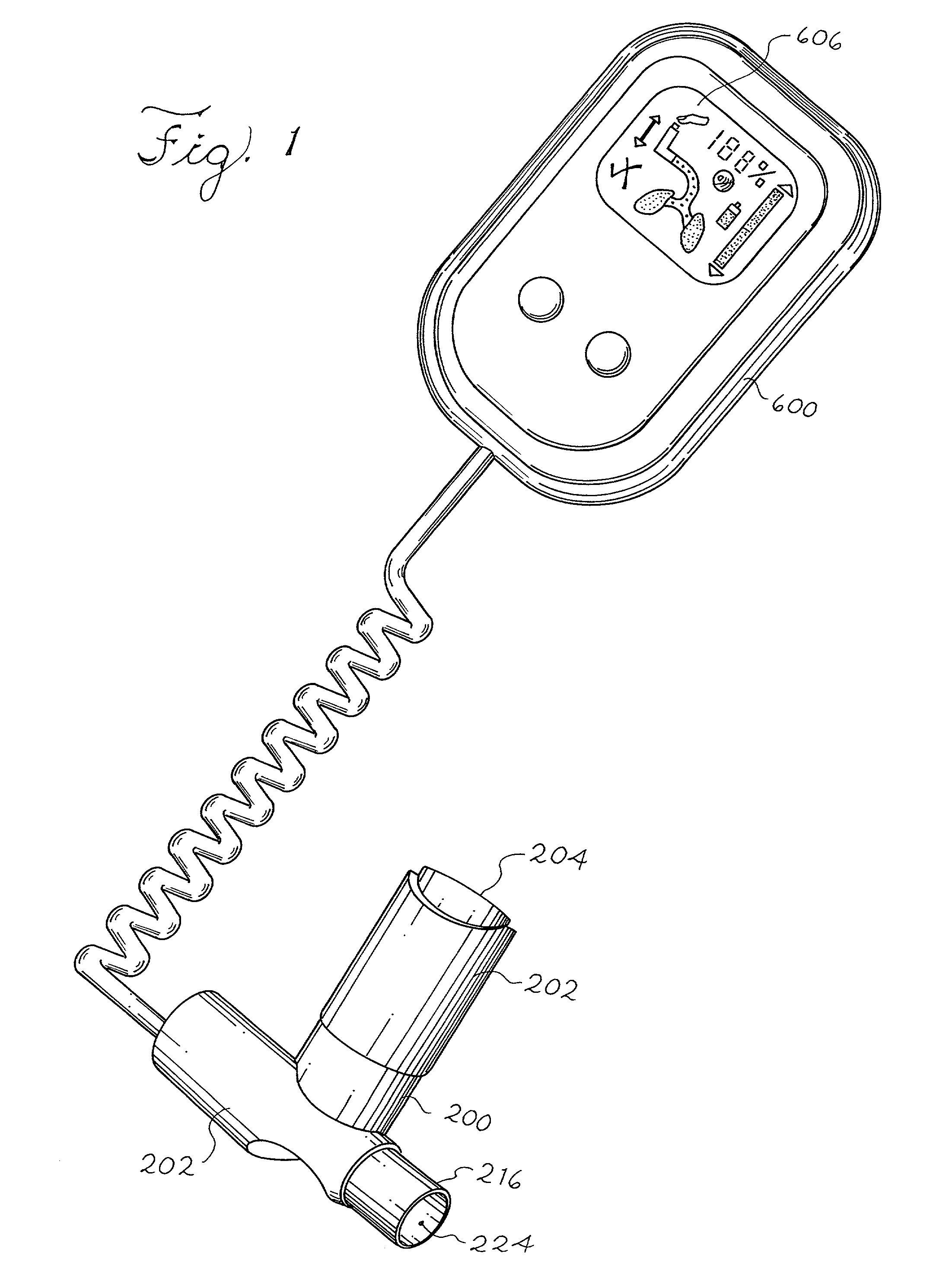
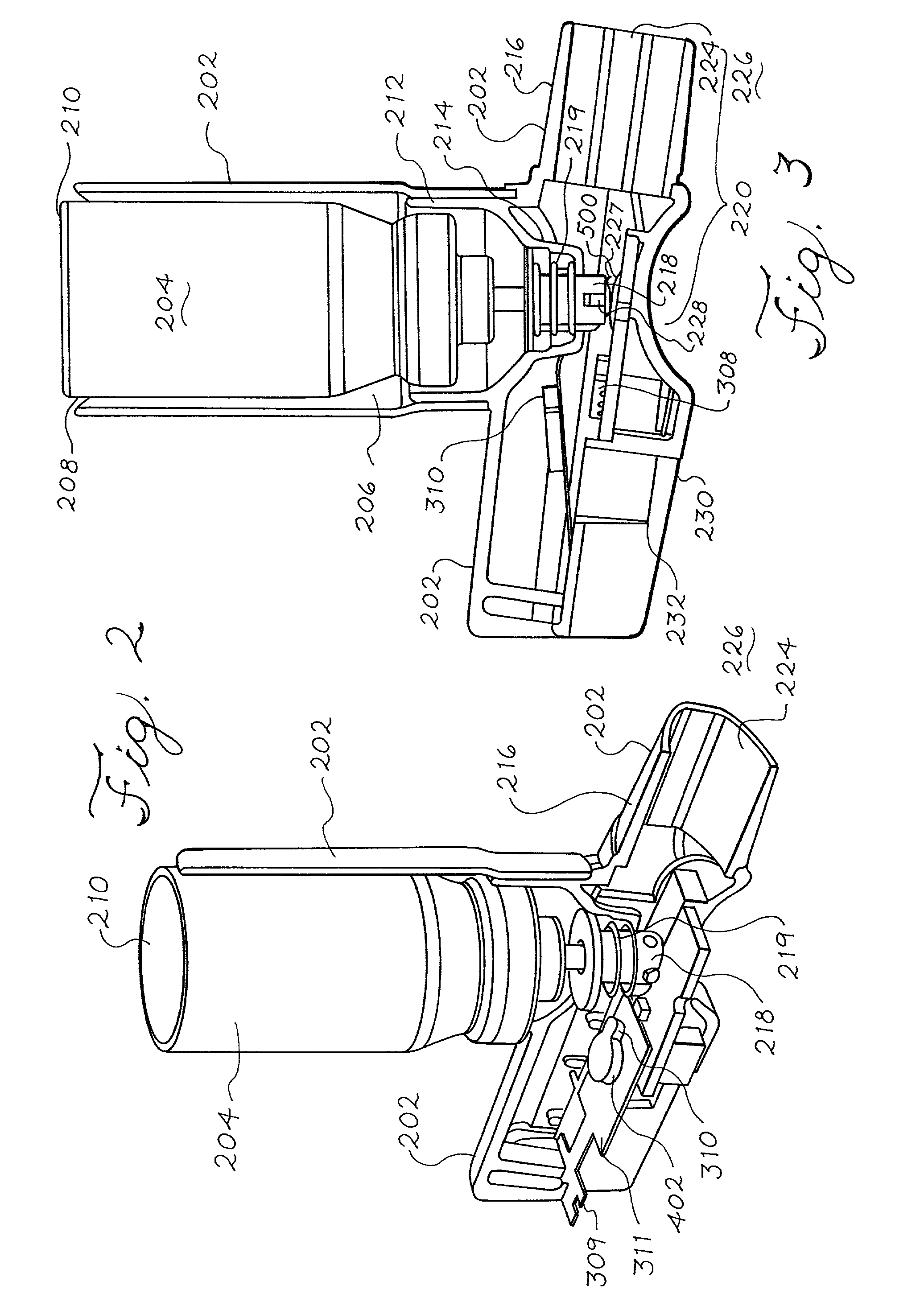
An aerosol dispensing inhaler training device for determining whether a user is properly operating an aerosol dispensing device. The training device includes an aerosol dispensing device having a container with a valve stem extending longitudinally therefrom and movable between a closed position and an open position. The container dispenses a portion of the contents within the container when the valve stem is moved to the open position. The aerosol dispensing device includes a housing adapted to support the container reciprocally moveable within the housing along a longitudinal axis from a first position, the housing comprising a well adapted to receive the valve stem and an exhaust port comprising one end in fluid communication with the well and a second end in fluid communication with the ambient atmosphere, wherein the portion of the contents within the container is dispensed from the first end of the exhaust port to the second end of the exhaust port when the housing moves to an actuation position where the valve stem is actuated so that a portion of the contents within the container is dispensed through the second end of the exhaust port when the valve stem is moved to the open position. An actuation sensor generates a signal that indicates when the housing is moved to the actuation position and the valve stem is actuated. A shake sensor determines whether the contents within the container have been properly agitated for consumption by a user.

Description

[0001] 1. Field of the Invention[0002] The present invention relates generally to an aerosol dispensing inhaler training device, and in particular, to an aerosol dispensing inhaler training device that can monitor several parameters, such as the flow rate, shaking of the container and the activation of the container comprising a solution or suspension which upon actuation transforms into an aerosol.[0003] 2. Description of Related Art[0004] Aerosol administered medication for bronchial therapy in such conditions as asthma, chronic bronchitis and emphysema is generally the preferred dosage technique for reasons of efficacy, reduced side effects and economy. Such particulate drugs are commonly prescribed using metered dose inhaler (MDI) type devices. It is well recognized that improper inhalation technique in the use of MDI devices is a serious barrier to effective therapy.[0005] Some patients may have difficulty in the use of conventional MDI devices especially in terms of controllin...

Claims


Application Information

Patent Timeline
Patent Type & Authority Applications(United States)
IPC IPC(8): A61B5/087A61M15/00A61M16/00
CPCA61B5/0876A61M15/0065A61M15/009A61M2016/0021A61M2205/52A61M15/0005A61M2205/332A61M15/008
Inventor STRUPAT, JOHN P.VERDUN, ALEX M.W.
Owner 1263152 ONTARIO
Why Eureka
Try Eureka