
Balloon displays

a technology for balloons and displays, applied in the field of balloons, can solve the problems of increasing the cost of making the joints, generating considerable waste, and relatively few systems specially designed and manufactured for these purposes

Inactive Publication Date: 2002-07-18
ROUSE GRAHAM MANLY
View PDF0 Cites 10 Cited by
  • Summary
  • Abstract
  • Description
  • Claims
  • Application Information

AI Technical Summary

Benefits of technology

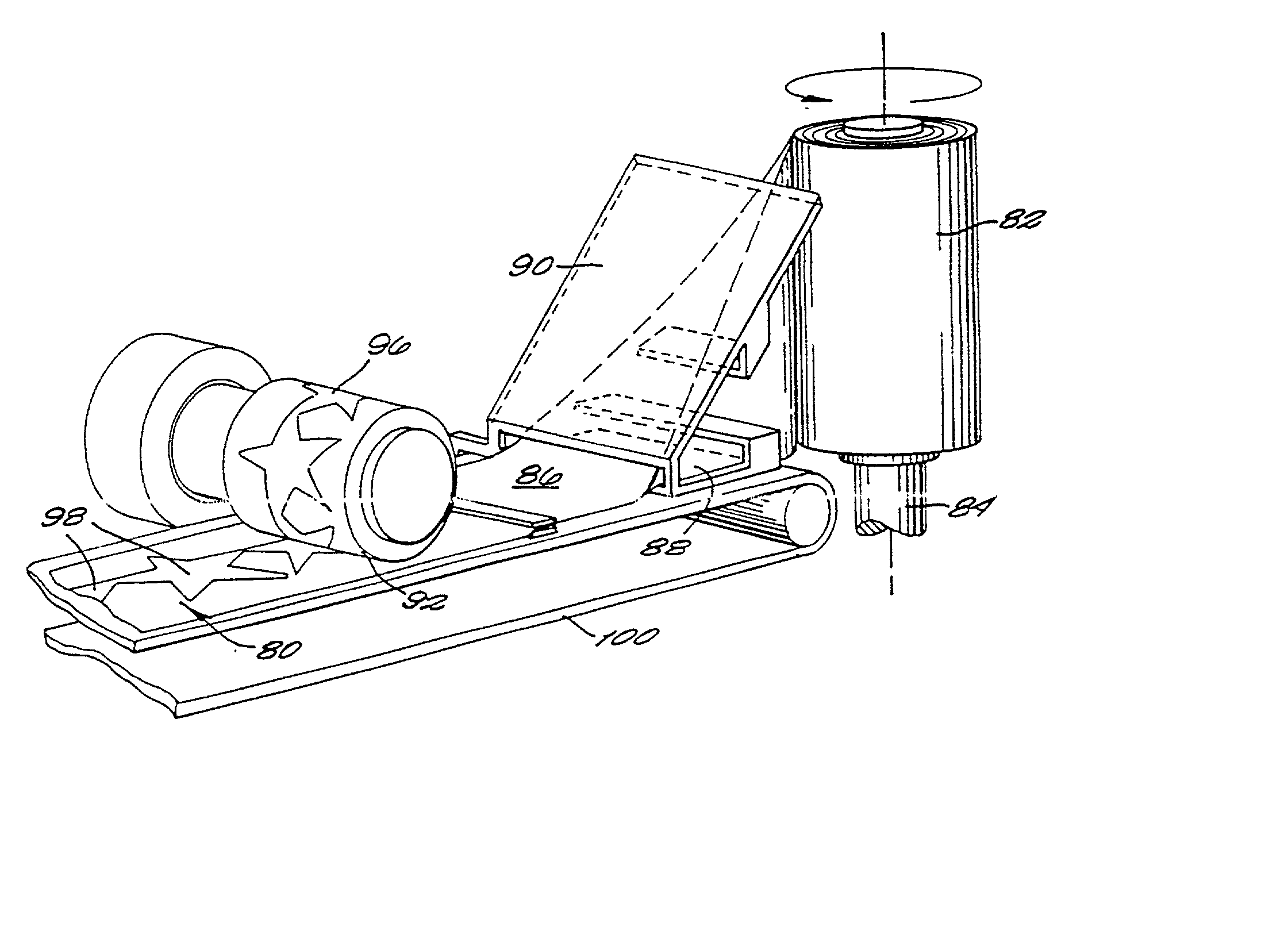
[0036] The balloon system is constructed primarily by the repeated application of the same die, a die that is formed to interconnect the shape so formed so that each balloonlet created by the die is automatically in fluid communication with the previous one formed. Additionally, certain features are incorporated into the interconnecting conduits so that the balloonlets maintain their alignment when inflated. Also, variations in the primary process are taught herein to allow variations in the chain of balloonlets. Because the balloon system is actually all one balloon, although it may appear to be dozens, perhaps thousands, of balloons, it has the advantage of being more easily inflated than individual balloons that would otherwise be needed to create the same display. To minimize the risk of puncture in a balloon system that is actually one large balloon, high quality, more puncture-resistant balloon films are preferred to latex rubber.
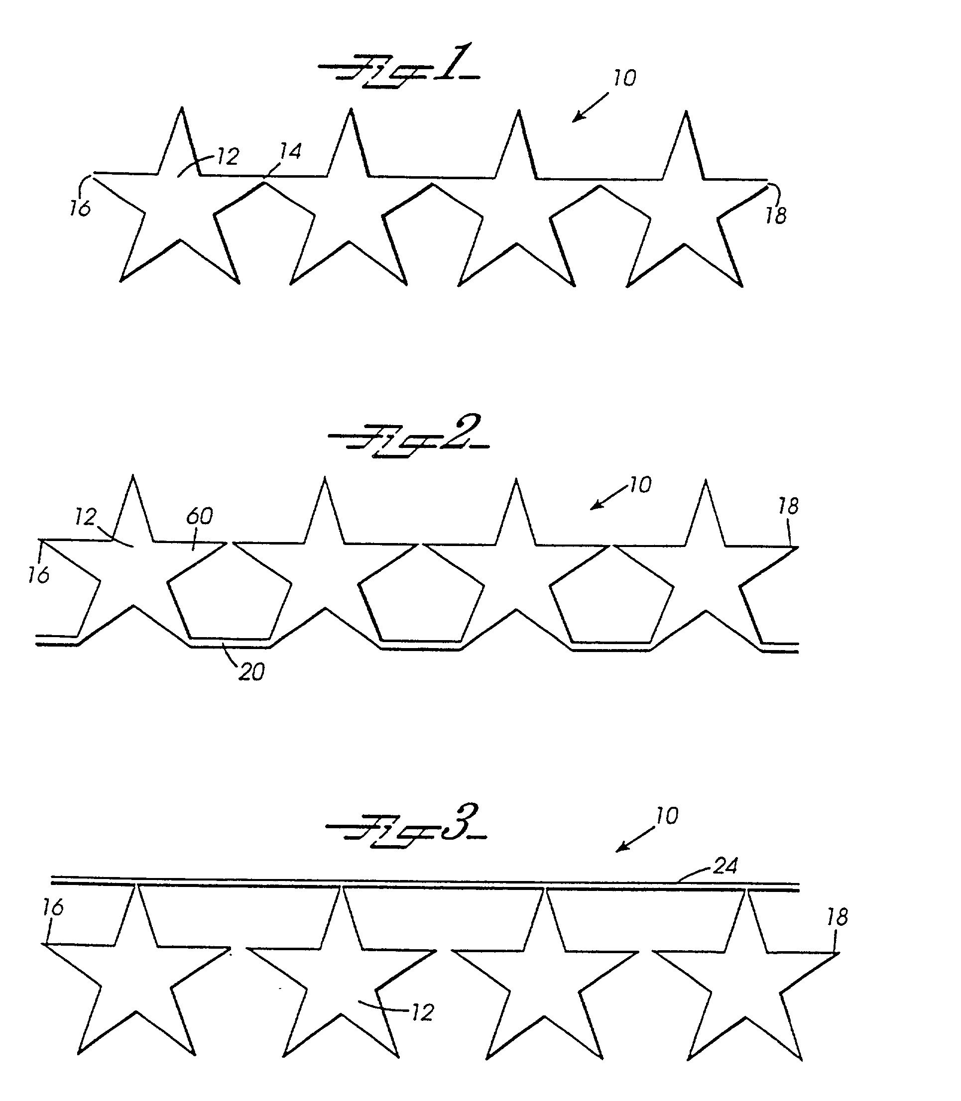
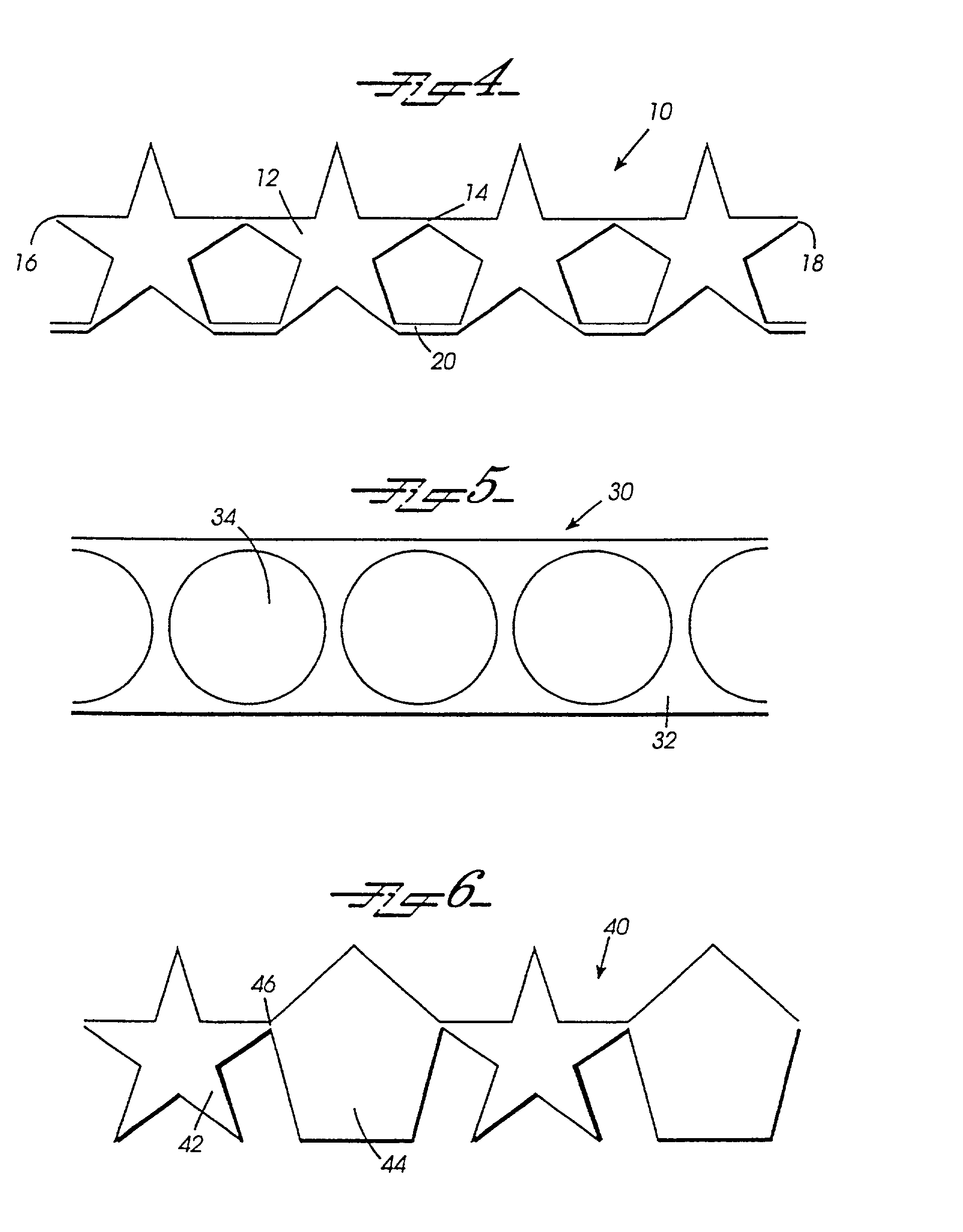
[0037] The grid structure that is used with the present balloon display is created under a third paradigm, as opposed to the first two described in the Background of the Invention. This paradigm begins with a structure similar to the formation of expanded metal grids for walkways, but by using certain techniques outlined herein, such as hooked and forked cuts and by shaping the material in certain ways, the result is a high degree of design flexibility. The present invention goes beyond standard overlapping cut expandable grids to produce a variety of expandable matrixes in flat shapes and patterns and in three dimensional forms not feasible under the preexisting state of the art. These cuts are generally made with an efficient die cut process as in the first paradigm, and yet, the thin character of the cuts minimizes waste material. Furthermore, none of the more costly assembling of elements required in the second paradigm is necessary. Because of the expandability of products manufactured under the third paradigm, the finished display may easily be five or more times the size of a manufactured framework. This efficiency of production and compactness along with related lighter weight are important advantages for uniting and connecting balloons into balloon displays.
[0038] Also, the cut is preferably made with rounded ends to avoid tearing the material. Many materials useful for balloon displays because they are light-weight, flexible, somewhat resilient and inexpensive are quite strong under tension, but rip easily once a tear has begun. Simple slits have the nature of a tear and, in such material, could render the sheets useless for the normal stresses of an overlapping cut expandable framework. By making careful cuts with smoothly rounded ends, the cut could take on the nature of an outer edge of the sheet rather than a tear. Even materials which resist ripping after a tear will be strengthened by the change to carefully made rounded ends to the cuts.
[0039] The simplest form of balloon system is a row of balloonlets. However, by the use of more complex dies, as would be best effected with a computer controlled laser sealing process, by use of more than two layers, and by use of a predetermined pattern of adhesive treatment, extraordinary structures can be created in three dimensions. These structures are single balloons, and when inflated, form passages, balloonlets, and openings for other balloons, balloon systems, and possibly other objects. The advantage of such a multidimensional balloon system is that complex three dimensional balloon shapes can be made of a single high-quality balloon for repeated use.

Problems solved by technology

There are, however, relatively few systems especially designed and manufactured for these purposes.
While these cut outs are generally accomplished with an efficient die cutting process, this paradigm generates considerable waste from the cut outs made in the processing.
Such an approach usually has less wasted material than in the first paradigm, but has the added expense of making those joints.
The finished display is limited to the size of the manufactured framework plus overhang from the connected balloons.
None of the current systems is particularly good for canopies or doubly curved surfaces.
Furthermore, none are manufactured to produce many popular solid shapes, although there are outline shapes for hearts and balloon nets in the shapes of hearts and stars.
One exception, however, is the use of paper clips or other wire hooks poked through the uninflated stem of the latex balloon, because films commonly used for balloons, although quite strong, tear easily once penetrated.
A second exception is pinching and twisting a film balloon across an inflated chamber, because the relatively inelastic nature of films makes such a procedure impractical.
Under current standard manufacturing methods for film balloons, a single die impression may produce multiple identical balloons either by repeated application or by one application of a complex die, however, the balloons thus created are not in fluid communication.
In order to save them for reuse, however, each balloon manufactured under current methods must be unsealed, deflated and packed for storage independently.
Simple slits have the nature of a tear and, in such material, could render the sheets useless for the normal stresses of an overlapping cut expandable framework.
Moreover, the fact that the present system can be easily deployed and taken down (i.e., deflated) for reuse, would justify the higher cost for premium materials.
It is not possible to eliminate this space entirely in standard expanded metal grids because the cuts are in a direct line and when the space is 0 all the cuts in a line will touch and the sheet will be cut into strips.

Method used


Image

  • Balloon displays
  • Balloon displays
  • Balloon displays

Examples


Embodiment Construction

, "fully expanded aperture" refers to the aperture shape which is created by equal pressures exerted from the center of a cut against the sides of that cut while that cut is surrounded by apertures which share a side, and each of the surrounding apertures has equal pressure exerted from the center of that aperture against its sides. As the space between the ends of adjacent cuts is reduced the two sides affected are shortened. It is not possible to eliminate this space entirely in standard expanded metal grids because the cuts are in a direct line and when the space is 0 all the cuts in a line will touch and the sheet will be cut into strips.

[0124] A "virtual" touching of cuts can, however, be created that allows the effective space between cuts to go to 0 without cutting the sheet into strips. The rows of slits or bands of slits can be viewed as multilane highways rather than single lane paths. As the slits approach each other down the center lane, one or both of them can shift lan...


PUM


Abstract

A structural and / or decorative balloon display is comprised of a plurality of connected, inflatable chambers formed by a plurality of die applications to a plurality of layers of film. In one preferred embodiment connected chambers have and maintain fluid communication. In another preferred embodiment, connected, inflatable chambers have no fluid communication. In other preferred embodiments fluid communication is terminated after inflation. Other embodiments take advantage of variations of numbers of layers, configurations of layers, and treatment of surfaces to create special balloon forms.

Description

[0001] 1. Field of the Invention[0002] The present invention is related generally to balloons for use as decoration and decorative architecture. More specifically, the present invention is related to systems for making and supporting balloon structures and displays. The present application claims the benefit of U.S. Provisional Application serial No. 60 / 008,096, filed Oct. 30, 1995.[0003] 2. Discussion of Background[0004] Balloons have been used as decorations for decades, but they have enjoyed increased usage in the recent past. There are two type of balloons commonly used for decor plus a variety of patented, specialty balloons.[0005] Balloons have traditionally been made of natural latex. Molds are dipped into a vat of liquid latex. Some of the latex adheres to the mold. The mold is removed and the adhered latex dries into a highly elastic membrane. The membrane is removed from the mold for use. The balloon thus created is usually a bulbous form with a single, narrow, tubular ste...

Claims


Application Information

Patent Timeline
IPC IPC(8): A63H27/10
CPCA63H27/10A63H2027/1025A63H2027/1075
Inventor ROUSE, GRAHAM MANLY
Owner ROUSE GRAHAM MANLY
Learn More