Gas lift valve with central body venturi for controlling the flow of injection gas in oil wells producing by continuous gas lift

a gas lift valve and valve body technology, applied in the direction of survey, directional drilling, borehole/well accessories, etc., can solve the problems of high cost, considerable flow restriction, and impaired good dynamic performance of the gas lift valv

Inactive Publication Date: 2002-07-25
PETROLEO BRASILEIRO SA (PETROBRAS)
View PDF0 Cites 28 Cited by
  • Summary
  • Abstract
  • Description
  • Claims
  • Application Information

AI Technical Summary

Problems solved by technology

However, laboratory tests indicate that in many cases a good dynamic performance of the gas lift valve can be impaired by the check valve, which is usually located immediately after the venturi.
Such check valve may cause a considerable constriction for the flow, in special in the situation where the features of the oil well require the use of venturis having throats of a large diameter for injecting significantly volumes of gas into the tubing.
The small space into a gas lift valve makes difficult to design a check valve which does not causes harmful effects to the dynamic performance of the gas lift valve.
Moreover, as the check valve has movable parts in small spaces, such check valve is a jeopardy for a reliable operation of the gas lift valve, as a malfunctioning of the check valve can lead to an intervention in the oil well in order to replace the gas lift valve.
In case the gas lift valve is installed in an undersea oil well, the costs for such intervention are very high.

Method used


Image

  • Gas lift valve with central body venturi for controlling the flow of injection gas in oil wells producing by continuous gas lift
  • Gas lift valve with central body venturi for controlling the flow of injection gas in oil wells producing by continuous gas lift
  • Gas lift valve with central body venturi for controlling the flow of injection gas in oil wells producing by continuous gas lift

Examples


Embodiment Construction

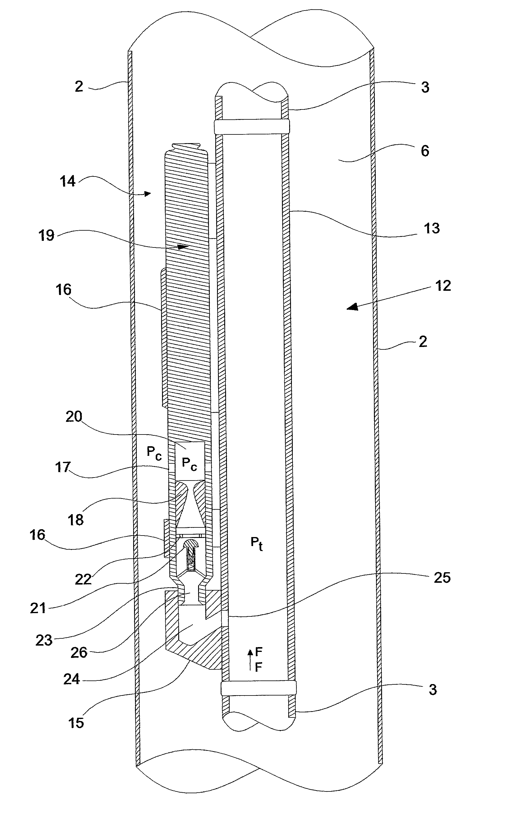
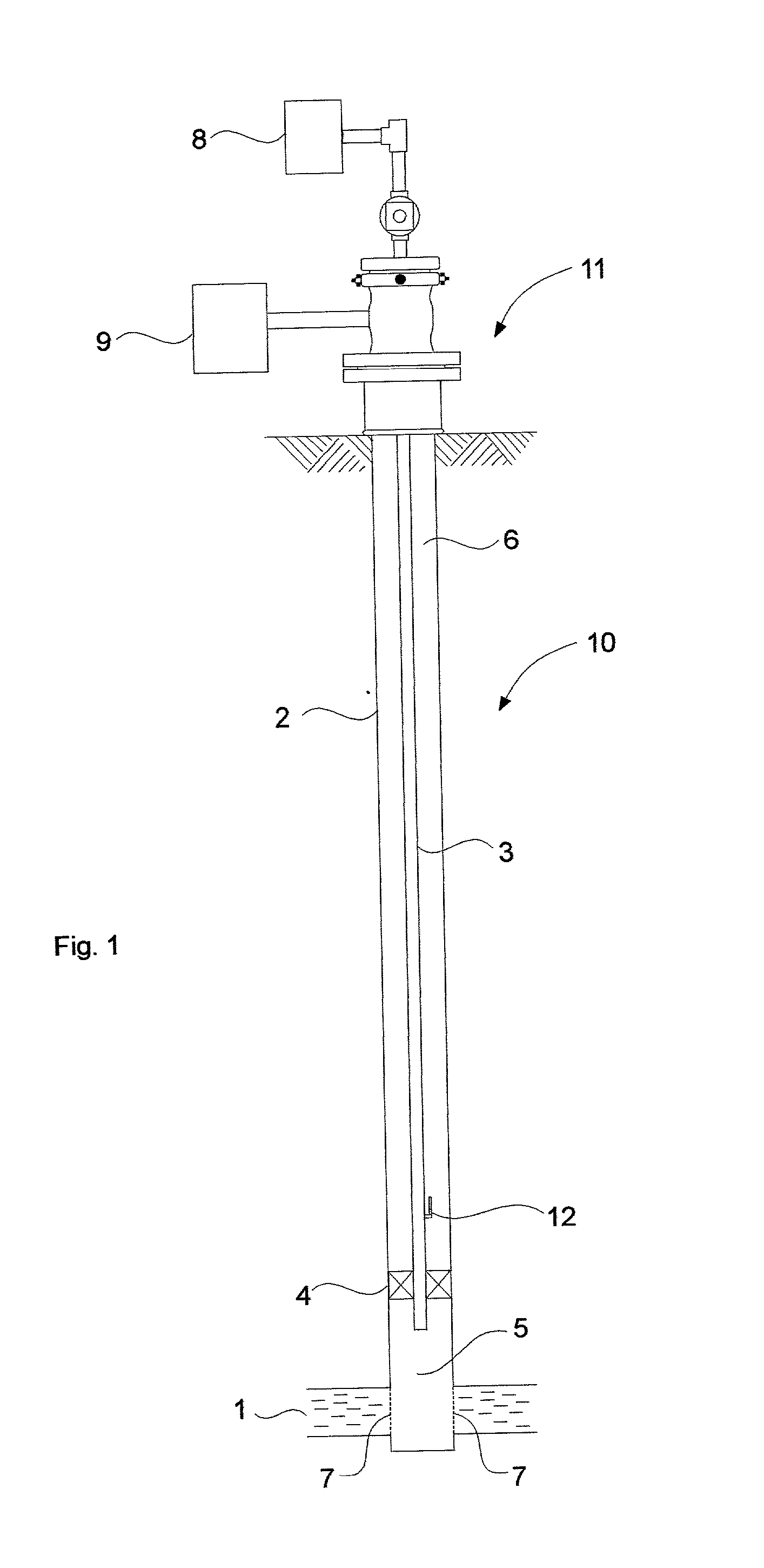
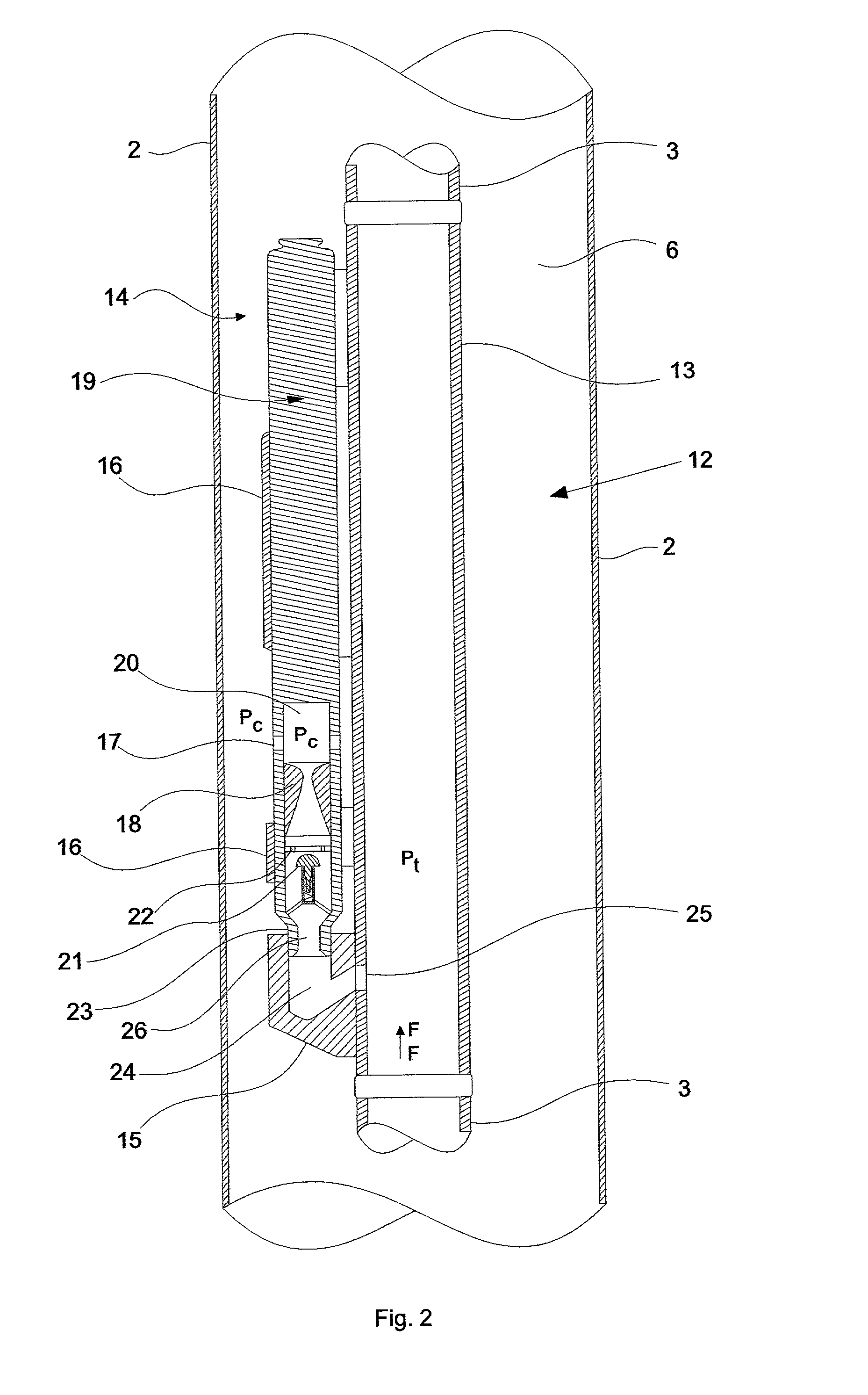
[0045] FIG. 1 is longitudinal cross sectional partial view which shows a typical gas lift facility, depicting an oil well 10 equipped to produce by means of continuous gas lift. Oil well 10 is basically a hole crossing a number of rock formations and extending from the surface to a reservoir 1. Oil well 10 is encased in its outermost part by a casing 2, a tubing 3 being inserted into said casing 2.

[0046] A packer 4 is installed in oil well 10, next to reservoir 1, and its function is to create two discrete zones into oil well 10, a first lower chamber 5, located next to reservoir 1, and a second upper chamber or annulus 6, formed between casing 2 and tubing 3, packer 4 providing a seal between the two chambers. At the surface there are facilities used to keep the operation of the well safe, which will be herein called as safety equipments and which are indicated in FIG. 1 by the numeral reference 11.

[0047] Fluids from reservoir 1 enter oil well 10 by means of small orifices 7, which...


PUM


Abstract

The present invention relates to a gas lift valve for use in an oil well producing by means of gas lift, said gas lift valve making use of a central body venturi for both controlling the flow of the injection gas from the annulus between the tubing and the casing of the oil well, and precluding a reverse flow of fluids from said oil well towards said annulus to occur.

Description

[0001] The present invention relates to a gas lift valve for use in an oil well producing by means of gas lift. More particularly, the present invention relates to a gas lift valve which makes use of a central body venturi for both controlling the flow of injection gas from an annulus between the tubing and the casing of the oil well, and precluding a reverse flow of fluids from the oil well to said annulus to occur.STATE OF THE ART[0002] Oil is usually found in accumulations under pressure in the subsoil, in porous and permeable sandstones known as reservoir stones, or simply reservoir, or yet producing rocking formations. Wells are drilled from the surface to drain off such reservoirs so as to communicate the reservoir with processing facilities in the surface, which are assembled to collect and to process the produced fluids.[0003] Wells are bores which cross several rocking formations. Usually a steel pipe is inserted in such bores, named casing. At least one pipe of smaller dia...

Claims


Application Information

Patent Timeline
Patent Type & Authority Applications(United States)
IPC IPC(8): E21B34/06E21B34/10E21B43/12E21B43/16F04FF04F1/20F16K15/02
CPCE21B43/123Y10T137/2934
Inventor DE ALMEIDA, ALCINO RESENDE
Owner PETROLEO BRASILEIRO SA (PETROBRAS)
Why Eureka
Try Eureka