
Imaging apparatus

a technology of image data and compensation, applied in the field can solve the problems of inability to memorize the content of image data compensation, the operative performance of the camera is reduced, and the need to wait a long time, so as to achieve the effect of quick compensation

Active Publication Date: 2002-07-25
MINOLTA CO LTD
View PDF4 Cites 27 Cited by
  • Summary
  • Abstract
  • Description
  • Claims
  • Application Information

AI Technical Summary

Benefits of technology

[0015] Still another purpose of this invention is to provide an imaging apparatus by which judgment of a condition of an object can properly executed in respective of the monitoring mode and the full image data outputting mode.
[0016] Still another purpose of this invention is to provide an imaging apparatus by which compensation process can properly be executed to an image data in respective of the monitoring mode and the full image data outputting mode.
[0018] By such a configuration, the image data outputted from the imaging device can be compensated corresponding to the result of judgment of the scene properly. For example, when the scene is judged as portrait, the image data is compensated in a manner so that the face portion can be reproduced natural and soft.
[0020] By such a configuration, the image data outputted from the imaging device can be compensated corresponding to the result of judgment of the condition of the object properly. For example, when it is judged that color fogging occurs, the image data is compensated so as to reduce the affect of the color fogging.
[0024] By such a system, the information corresponding to the scene or the condition of the object judged in the imaging apparatus can be used for reproducing the image by the image outputting apparatus. Thus, the image data can properly be compensated corresponding to the judgment of the scene or the condition of the object in the image outputting apparatus.
[0026] By such a configuration, the first image data used for displaying the monitor image serving as the viewfinder can quickly be compensated, and the second image data to be recorded in the recoding medium can properly be compensated by different compensation process from that for the first image data.

Problems solved by technology

The conventional camera, however, merely memorizes the position information of the selected area as the main object, but contents of the image data compensation are not memorized.
Thus, it is necessary to wait a long time for printing an image of the object.
Thus, the processes for selecting the main objects becomes troublesome, and the operative performance of the camera becomes lower.

Method used


Image

  • Imaging apparatus
  • Imaging apparatus
  • Imaging apparatus

Examples


Embodiment Construction

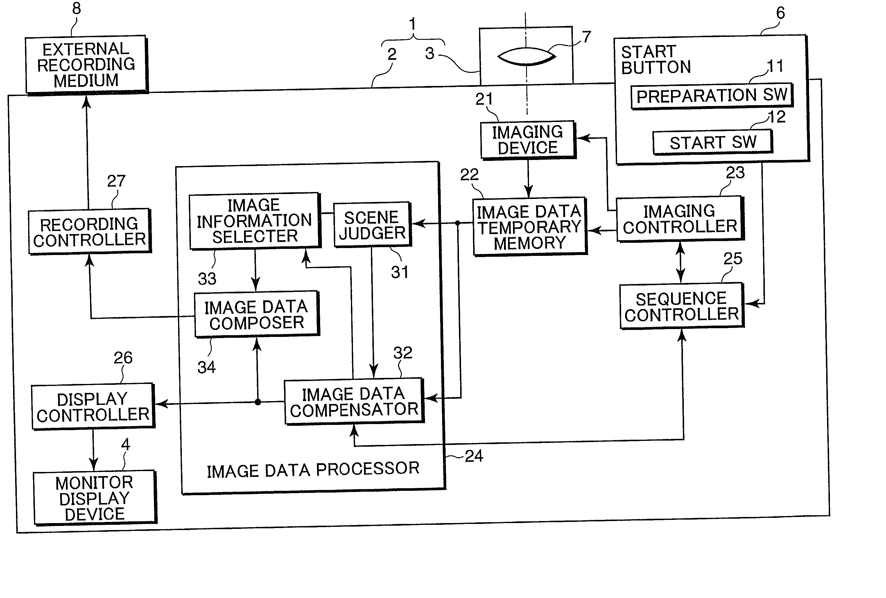
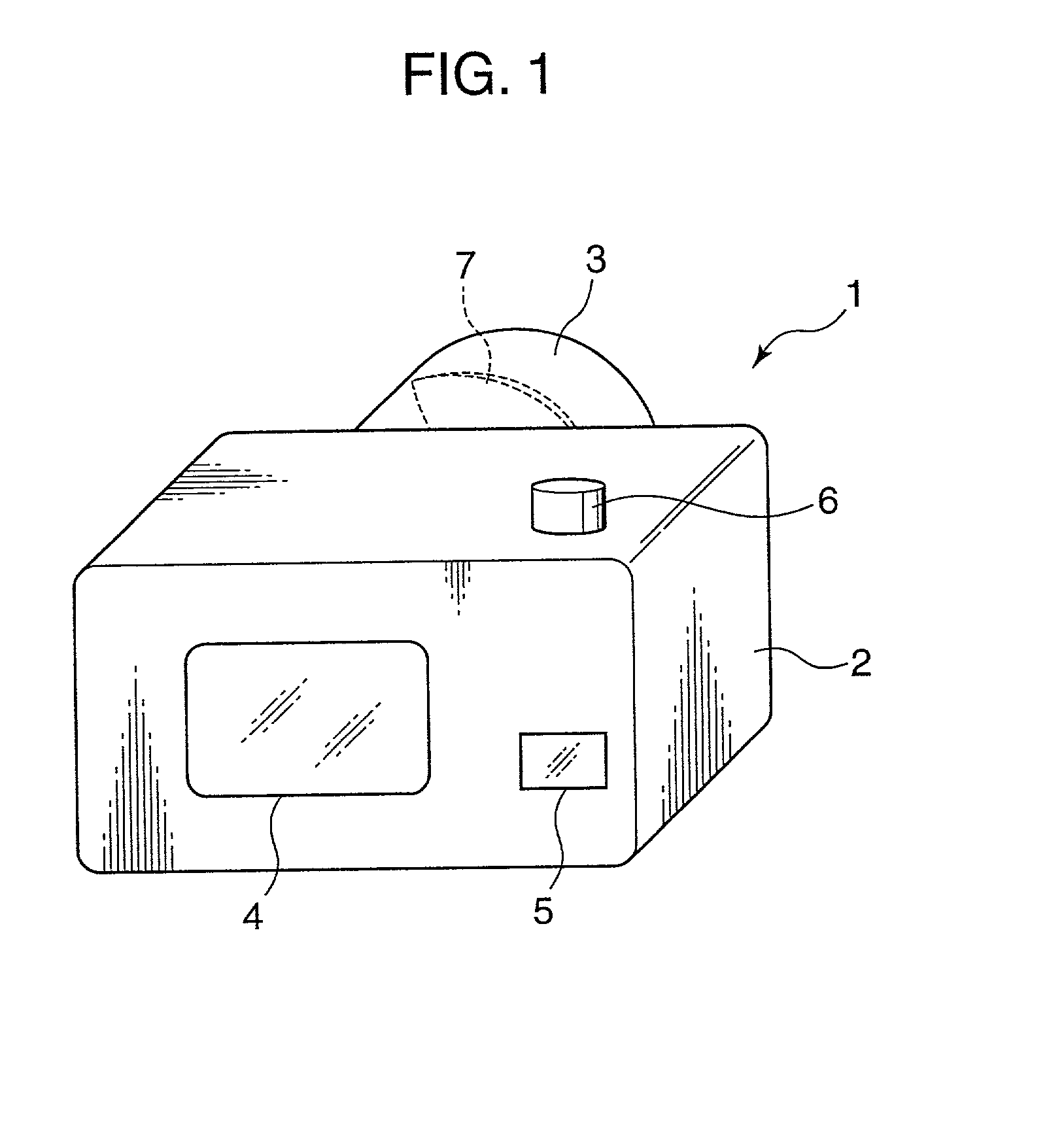
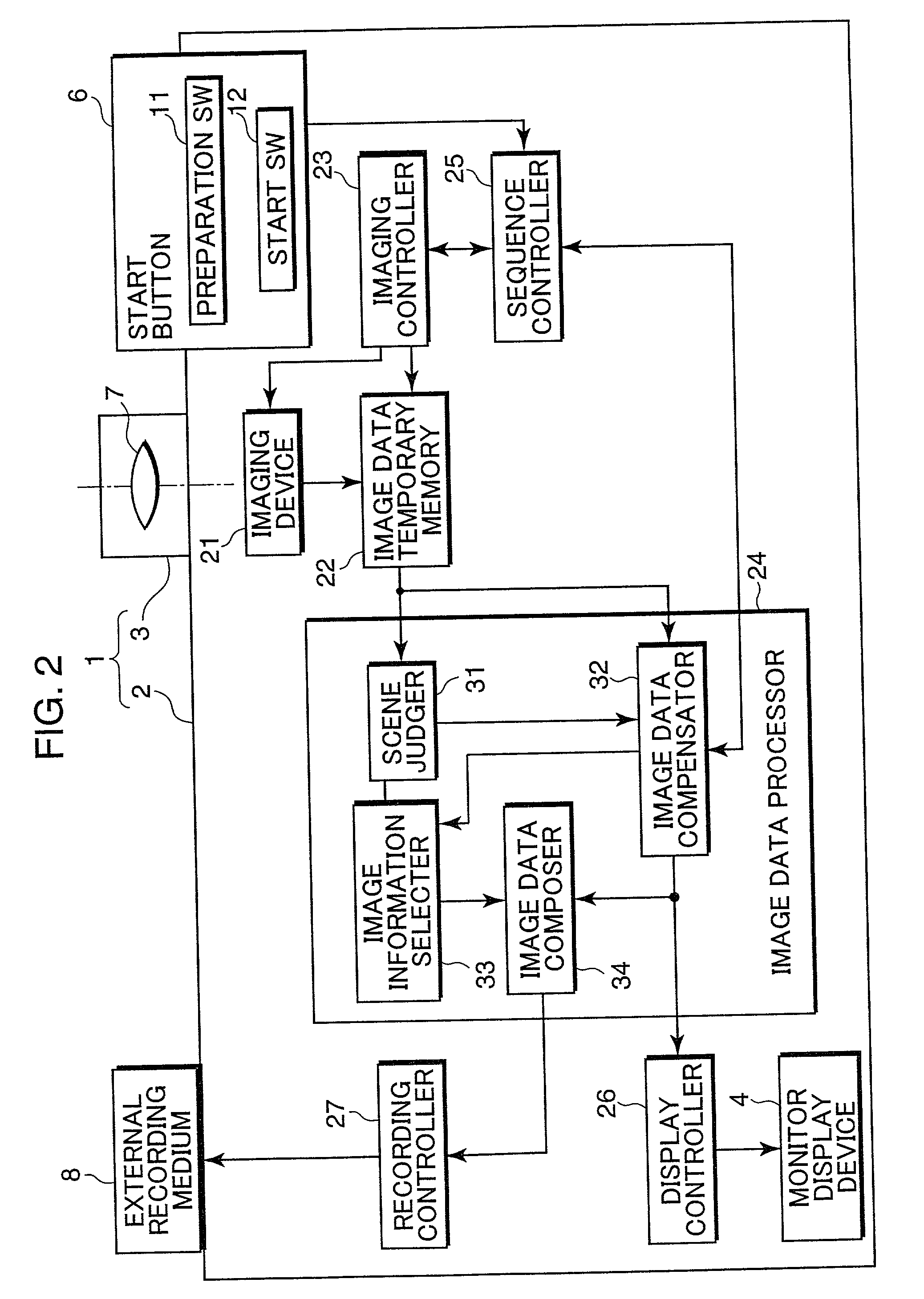
[0050] An embodiment of this invention is described with reference to the figures. FIG. 1 is a perspective view of a digital still camera which is an example of an imaging apparatus in accordance with this embodiment. FIG. 2 is a block diagram of the digital still camera in this embodiment.

[0051] As can be seen from FIG. 1, the digital still camera 1 comprises a camera body 2 and a taking lens 3. A monitor display device 4 including an LCD (Liquid Crystal Display) and a memory recorder 5 to which an external recording medium 8 (see FIG. 2) such as a memory card can be inserted to be recorded are provided on a rear face of the camera body 2. A shutter start button 6 (hereinafter, it is called "start button 6) is provided at a right side on a top face of the camera body 2. An optical lens system 7 is provided in the inside of a lens barrel of the taking lens 3.

[0052] The digital still camera 1 has functions for taking an image data of an object, for executing compensation processes su...


PUM


Abstract

In an imaging apparatus such as a digital still camera, a scene is judged with using an image data outputted from an area sensor in a preparation state in which an image displayed on a monitor display serves as a viewfinder, and another image data to be recorded in a recording medium in an image recording mode is compensated corresponding to a result of judgment of the scene. By such the compensation, an image using the image data recorded in the recording medium can properly be reproduced by an image outputting apparatus such as a printer.

Description

[0001] This application is based on patent applications 2001-014301 and 2001-014302 filed in Japan, the contents of which are hereby incorporated by references.[0002] 1. Field of the Invention[0003] This invention relates to an imaging apparatus having functions for judging a condition with respect to an object and for compensating an image data of the object by basing on the result of the judgment.[0004] 2. Description of the Related Art[0005] In a field of a digital still camera using an imaging device such as a CCD or a CMOS, a first conventional camera enabling image taking, image reproducing and image printing processes with attaching importance to a main object selected by a user is conventionally proposed, for example, in Publication Gazette of Japanese Patent Application Hei 11-136568.[0006] The conventional camera has a display panel by which a position or an area of a main object on the display panel can be selected before taking an image of the object. When the image of t...

Claims


Application Information

Patent Timeline
Patent Type & Authority Applications(United States)
IPC IPC(8): H04N1/21H04N1/23
CPCH04N1/21H04N1/23H04N2201/0082H04N2201/3242H04N2201/3252H04N2201/3254
Inventor HARA, YOSHIHIROIZUME, RIEKO
Owner MINOLTA CO LTD
Learn More