Electric distribution device, installation comprising such a device, and electrical protection process

a technology of electric distribution device and installation process, which is applied in the direction of emergency protection arrangement for limiting excess voltage/current, and arrangement responsive to excess current, etc., can solve the problem that state of the art devices do not enable easy management of electrical system installation, and achieve the effect of improving reliability and endurance and easy managemen

Inactive Publication Date: 2002-07-25
SCHNEIDER ELECTRIC IND SAS
View PDF10 Cites 24 Cited by
  • Summary
  • Abstract
  • Description
  • Claims
  • Application Information

AI Technical Summary

Benefits of technology

[0010] The object of the invention is to provide an electrical distribution device having improved reliability and endurance and enabling easy management of an electrical installation, an installation comprising such a device, and an electrical protection process improving reliability and electrical protection fault management.

Problems solved by technology

State of the art devices do not enable easy management of electrical system installation.

Method used


Image

  • Electric distribution device, installation comprising such a device, and electrical protection process
  • Electric distribution device, installation comprising such a device, and electrical protection process
  • Electric distribution device, installation comprising such a device, and electrical protection process

Examples


first embodiment

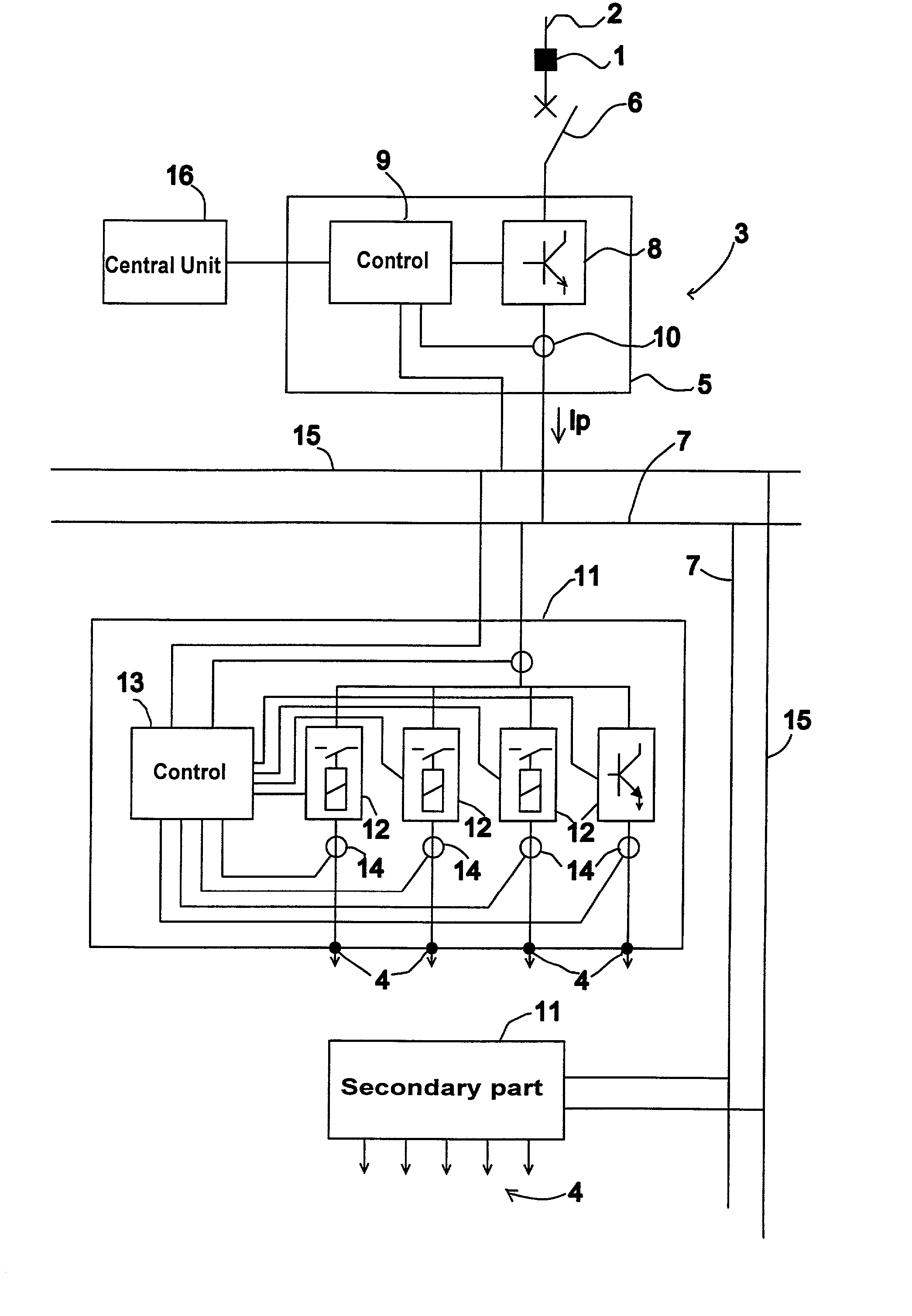
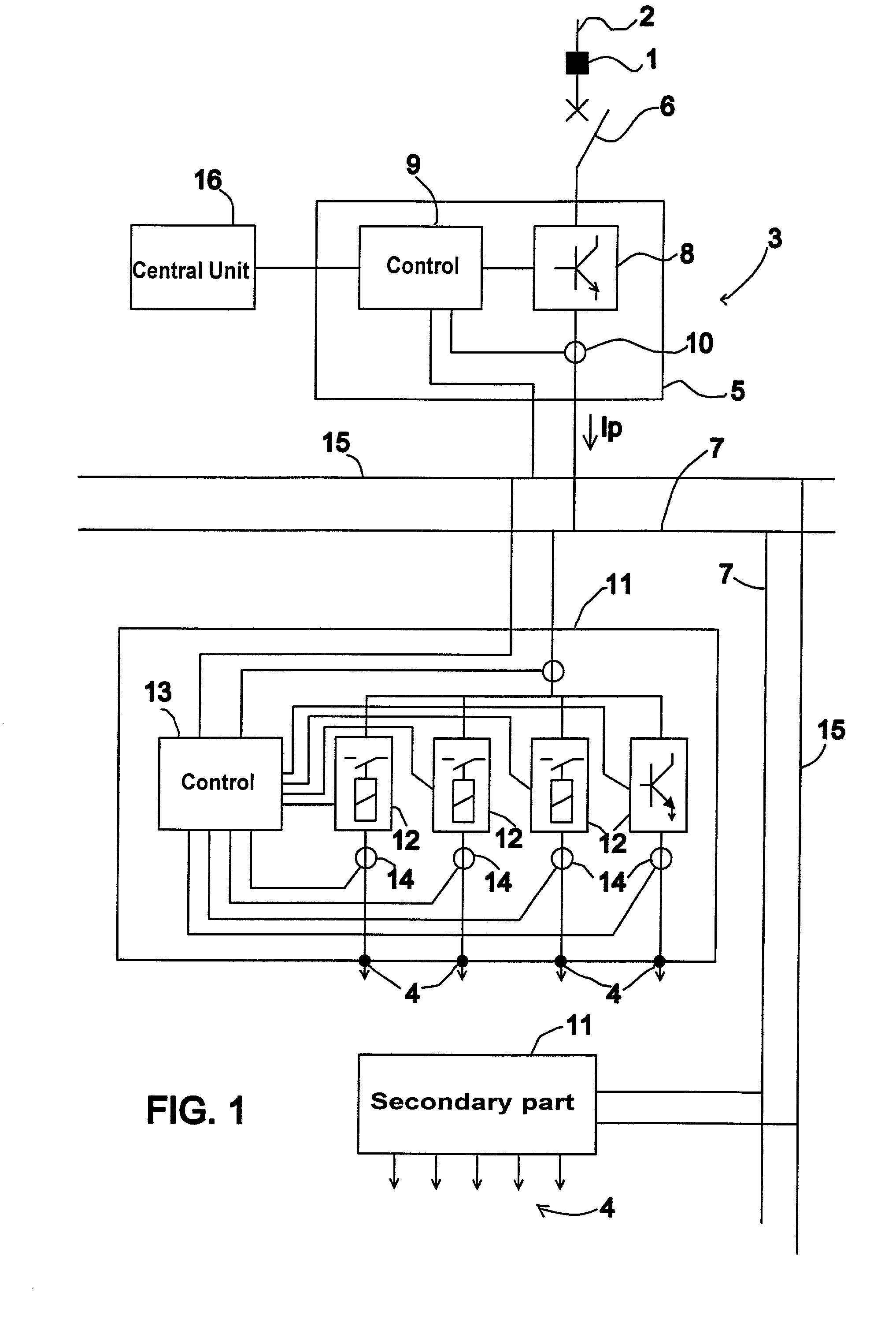
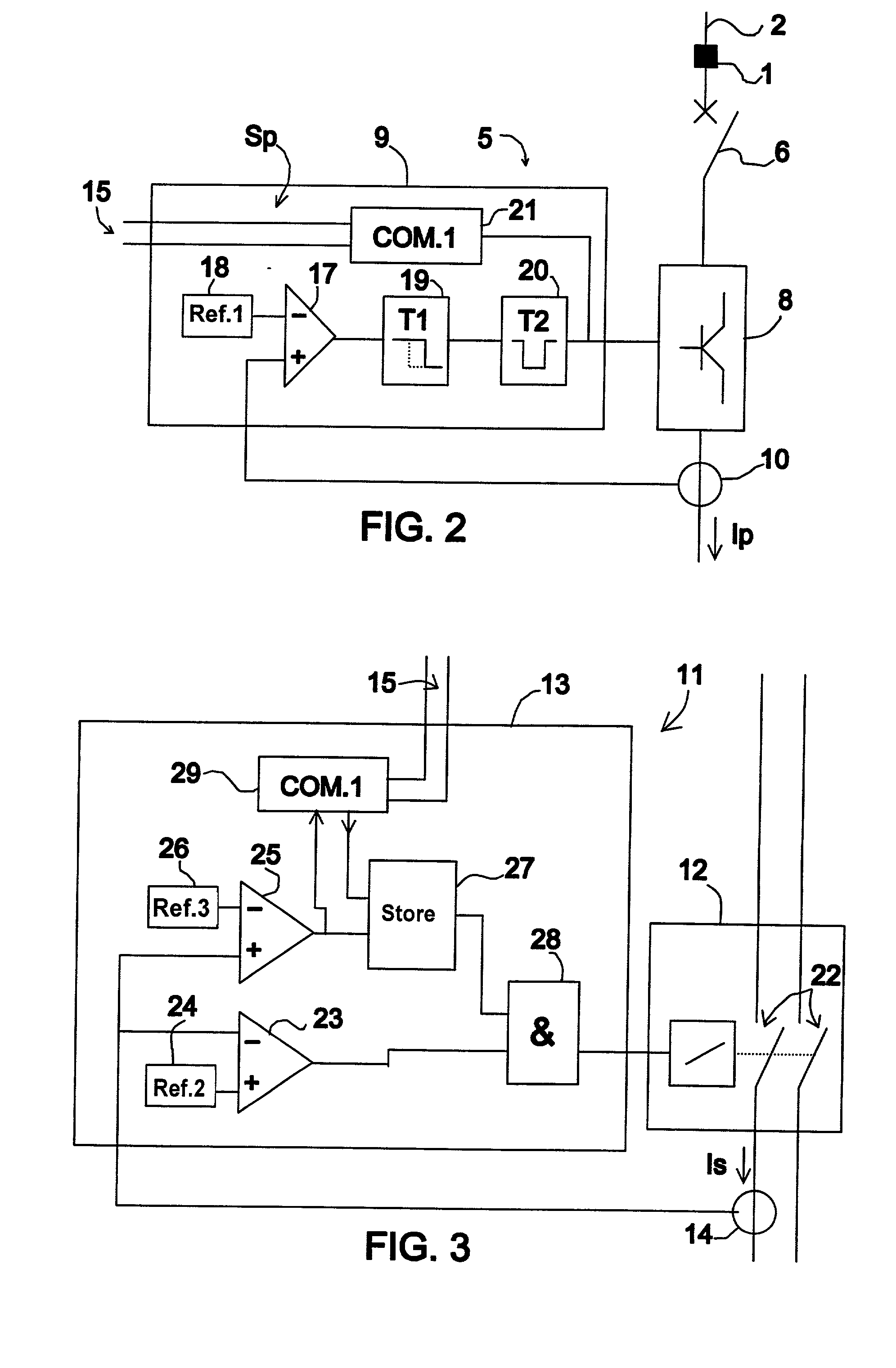
[0069] FIGS. 4A, 4B and 4C illustrate operating curves of a device according to a In FIG. 4A, two curves 30 and 31 represent a short-circuit current detected by a current sensor 10 detecting the main current Ip and a current sensor 14 detecting a secondary current Is, and a curve 32 represents an unbroken prospective short-circuit current. FIG. 4B represents control of a main breaking device 8 and FIG. 4C represents control of a secondary breaking device 12.

[0070] At a time t1, the current Is in a secondary breaking device exceeds a detection threshold S3 of an electrical fault in a secondary control circuit 13. Then at a time t2, the current Ip exceeds a current detection threshold S1 of an electrical fault in a main control circuit 9. After a time delay T1 of short duration, at a time t3, opening of the main breaking device is commanded and the secondary breaking device remains closed. Then at a time t4, the secondary current Is drops below an opening threshold S2 and opening of ...

second embodiment

[0071] FIGS. 5A, 5B, 5C and 5D illustrate operating curves of a device according to a In FIG. 5A, two curves 30 and 31 represent a short-circuit current detected by a current sensor 10 detecting the main current Ip and a current sensor 14 detecting the secondary current Is. FIG. 5B represents signals on a communication line 15 on which communication signals 33 and a particular priority signal Sp can be transmitted. FIG. 5C represents command of a main breaking device 8 and FIG. 5D represents command of a secondary breaking device 12.

[0072] At a time t10, a secondary current Is exceeds a detection threshold S3 of an electrical fault in a secondary control circuit 13. The circuit 13 then forces a signal Sp on the communication line 15 and the communication signal frames 33 are interrupted. A main control circuit 5 detects the particular priority signal Sp and commands opening of the main breaking device 8. The currents Ip and Is decrease, then at the time t11 the control circuit 13 d...


PUM


Abstract

The electrical distribution device comprises a main part comprising main breaking means, at least one secondary part comprising at least one secondary breaking device, and an electrical power distribution line connected between the main and secondary parts. The secondary part comprises secondary control means enabling opening of at least one secondary breaking device if a current flowing in said breaking device is lower than a preset opening current threshold. A distributed electrical installation comprises at least one such device. An electrical protection process for an electrical distribution device comprises an opening step of the secondary breaking means when a current flowing in these means is lower than a preset opening current threshold following detection of a fault.

Description

[0001] The invention relates to an electrical distribution device comprising an input for connection of an incoming electrical line, electrical protection means connected to the input and comprising electrical distribution feeders designed to supply electrical loads, said protection means comprising:[0002] a main part comprising main breaking means connected to the input for connecting the incoming electrical line, and main control means for controlling opening and closing of the main breaking means, and[0003] an electrical power distribution line connected to the main breaking means of the main part.[0004] The invention also relates to an installation comprising an incoming electrical line, an electrical distribution device connected to the incoming electrical line, and distribution lines connected between the electrical distribution device and electrical apparatuses or loads. The invention also relates to an electrical protection process for an electrical distribution device.[0005...

Claims


Application Information

Patent Timeline
Patent Type & Authority Applications(United States)
IPC IPC(8): H02H7/22H02H7/30
CPCH02H7/222H02H7/30
Inventor PERICHON, PIERRE
Owner SCHNEIDER ELECTRIC IND SAS
Why Eureka
Try Eureka