Electric distribution device, installation comprising such a device, and electrical protection process
a technology of electric distribution device and installation process, which is applied in the direction of emergency protection arrangement for limiting excess voltage/current, and arrangement responsive to excess current, etc., can solve the problem that state of the art devices do not enable easy management of electrical system installation, and achieve the effect of improving reliability and endurance and easy managemen
- Summary
- Abstract
- Description
- Claims
- Application Information
AI Technical Summary
Benefits of technology
Problems solved by technology
Method used
Image
Examples
first embodiment
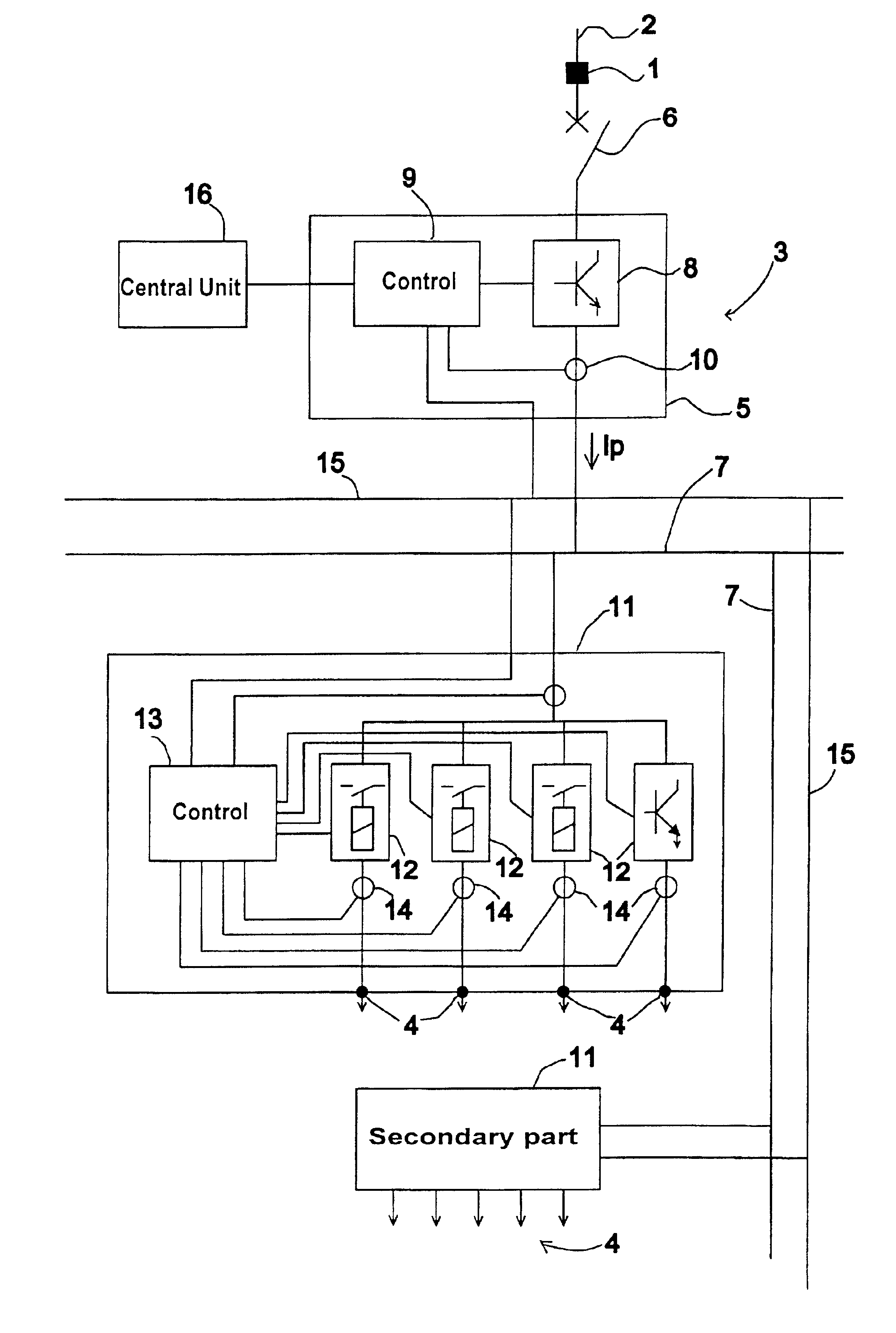
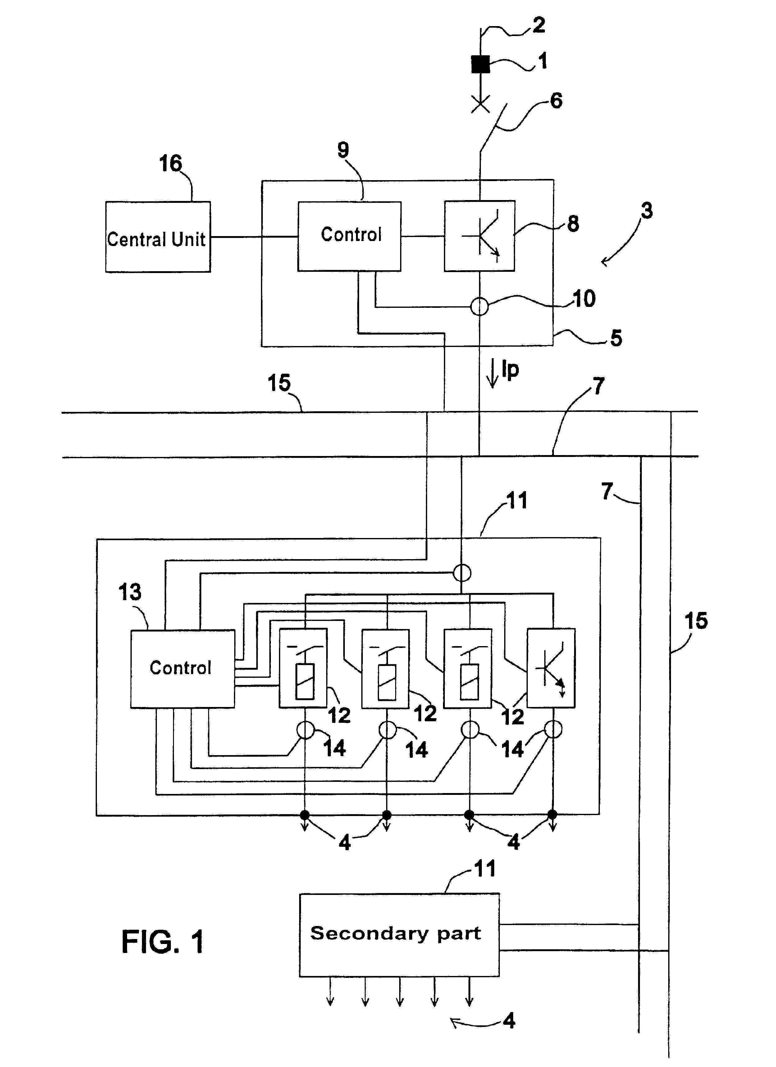
FIGS. 4A, 4B and 4C illustrate operating curves of a device according to a In FIG. 4A, two curves 30 and 31 represent a short-circuit current detected by a current sensor 10 detecting the main current Ip and a current sensor 14 detecting a secondary current Is, and a curve 32 represents an unbroken prospective short-circuit current. FIG. 4B represents control of a main breaking device 8 and FIG. 4C represents control of a secondary breaking device 12.
At a time t1, the current Is in a secondary breaking device exceeds a detection threshold S3 of an electrical fault in a secondary control circuit 13. Then at a time t2, the current Ip exceeds a current detection threshold S1 of an electrical fault in a main control circuit 9. After a time delay T1 of short duration, at a time t3, opening of the main breaking device is commanded and the secondary breaking device remains closed. Then at a time t4, the secondary current Is drops below an opening threshold S2 and opening of the secondary ...
second embodiment
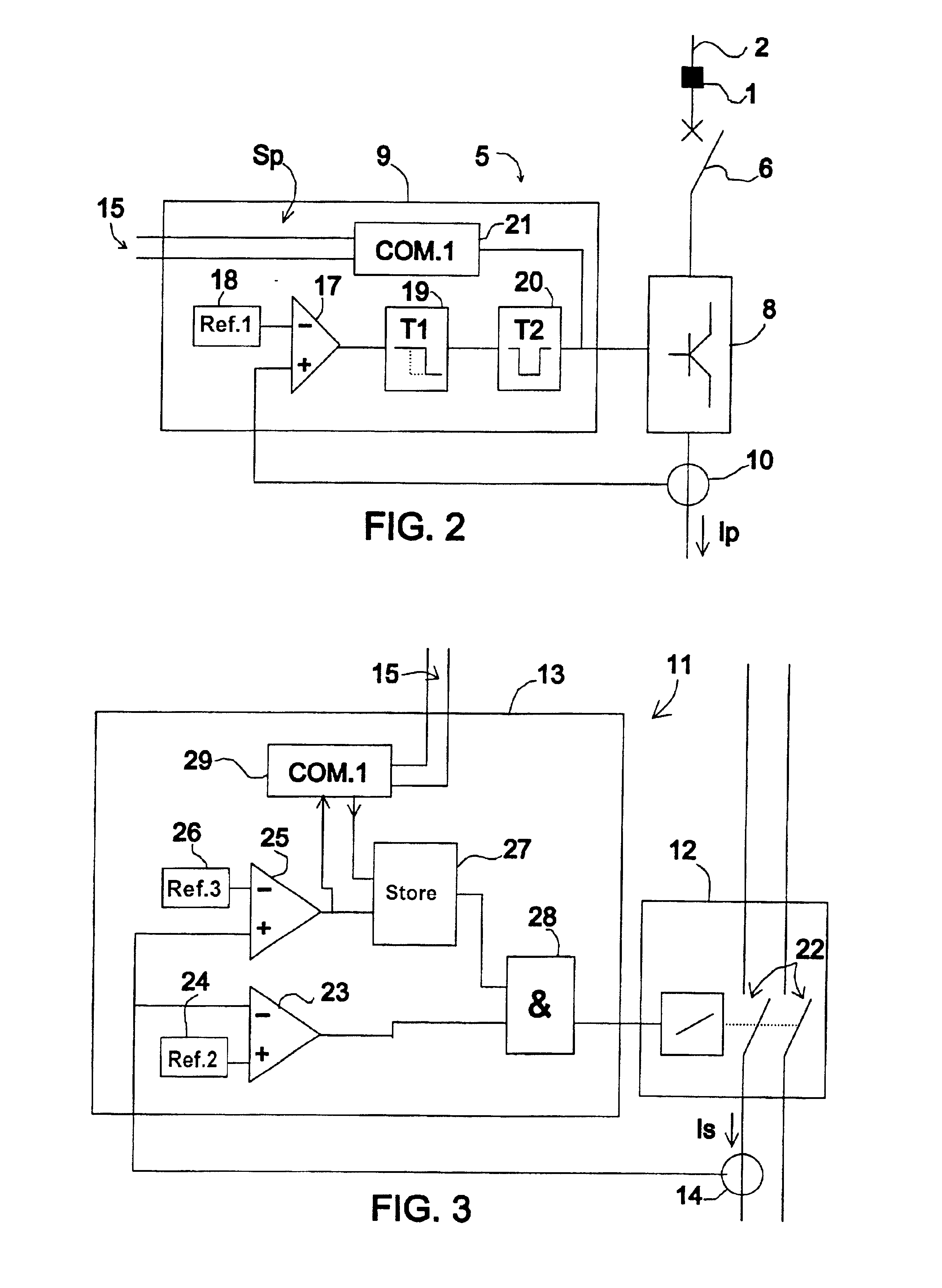
FIGS. 5A, 5B, 5C and 5D illustrate operating curves of a device according to a In FIG. 5A, two curves 30 and 31 represent a short-circuit current detected by a current sensor 10 detecting the main current Ip and a current sensor 14 detecting the secondary current Is. FIG. 5B represents signals on a communication line 15 on which communication signals 33 and a particular priority signal Sp can be transmitted. FIG. 5C represents command of a main breaking device 8 and FIG. 5D represents command of a secondary breaking device 12.
At a time t10, a secondary current Is exceeds a detection threshold S3 of an electrical fault in a secondary control circuit 13. The circuit 13 then forces a signal Sp on the communication line 15 and the communication signal frames 33 are interrupted. A main control circuit 5 detects the particular priority signal Sp and commands opening of the main breaking device 8. The currents Ip and Is decrease, then at the time t11 the control circuit 13 detects Is drop...
PUM
 Abstract
Description
Claims
Application Information
 - R&D
- Intellectual Property
- Life Sciences
- Materials
- Tech Scout
- Unparalleled Data Quality
- Higher Quality Content
- 60% Fewer Hallucinations
Browse by: Latest US Patents, China's latest patents, Technical Efficacy Thesaurus, Application Domain, Technology Topic, Popular Technical Reports.
© 2025 PatSnap. All rights reserved.Legal|Privacy policy|Modern Slavery Act Transparency Statement|Sitemap|About US| Contact US: help@patsnap.com


