Enhanced oil well production system

a production system and oil well technology, applied in the direction of wellbore/well accessories, sealing/packing, insulation, etc., can solve the problems of reducing production rates, choking off the flow of material to the surface, and high percentage of paraffin in oil, so as to increase the oil production rate and increase the oil production.

Inactive Publication Date: 2002-08-01
HAWKEN GORDON GERALD MR
View PDF0 Cites 19 Cited by
  • Summary
  • Abstract
  • Description
  • Claims
  • Application Information

AI Technical Summary

Benefits of technology

0008] The present invention provides a method of increasing oil production from a downhole formation through a production tubing to a wellhead. One embodiment of the method comprises heating a working fluid at the wellhead and circulating the heated working fluid through a conduit that is secured in thermal communication with the production tubing. The conduit extends from a heating system adjacent the wellhead to a downhole pump at a distal end of the production tubing and back to the heating system. Preferably, the rate of heat transfer from the working fluid to the oil in the production tubing is controlled to increase the rate of oil production. The step of controlling the rate of heat transfer may include a step selected from controlling the temperature of the working fluid exiting the heating system, controlling the rate of circulating the working fluid, or a combination thereof. It is preferred that the conduit allow for the expansion of the working fluid. It is also preferred to monitor the temperature of the oil produced from the production tubing at the wellhead and monitor the flow rate of the oil produced from the production tubing at the wellhead. The method provides the ability to control the working fluid temperature exiting the heating system to produce a desired flow rate of the oil.

Problems solved by technology

Another problem arises when oils contain a high percentage of paraffins.
These deposits of paraffin restrict the flow of oil and will eventually choke off the flow of material to the surface.
The resulting restricted flow not only reduces production rates but causes premature failure of the pump located in the oil reservoir and premature failure of the sucker rods in walking beam pumps and other type of pumps that are located whole in the reservoir area, an example of which would be a submersible pump.
The result of this buildup causes a periodic shutdown of the well for various types of cleaning.
Additionally, the use of other methods of warming the oil, such as using other precious resources like water, are considered to be inappropriate since there is a danger that the water would become contaminated by oil, or other chemical components located below the earth's surface.

Method used


Image

  • Enhanced oil well production system
  • Enhanced oil well production system
  • Enhanced oil well production system

Examples


Embodiment Construction

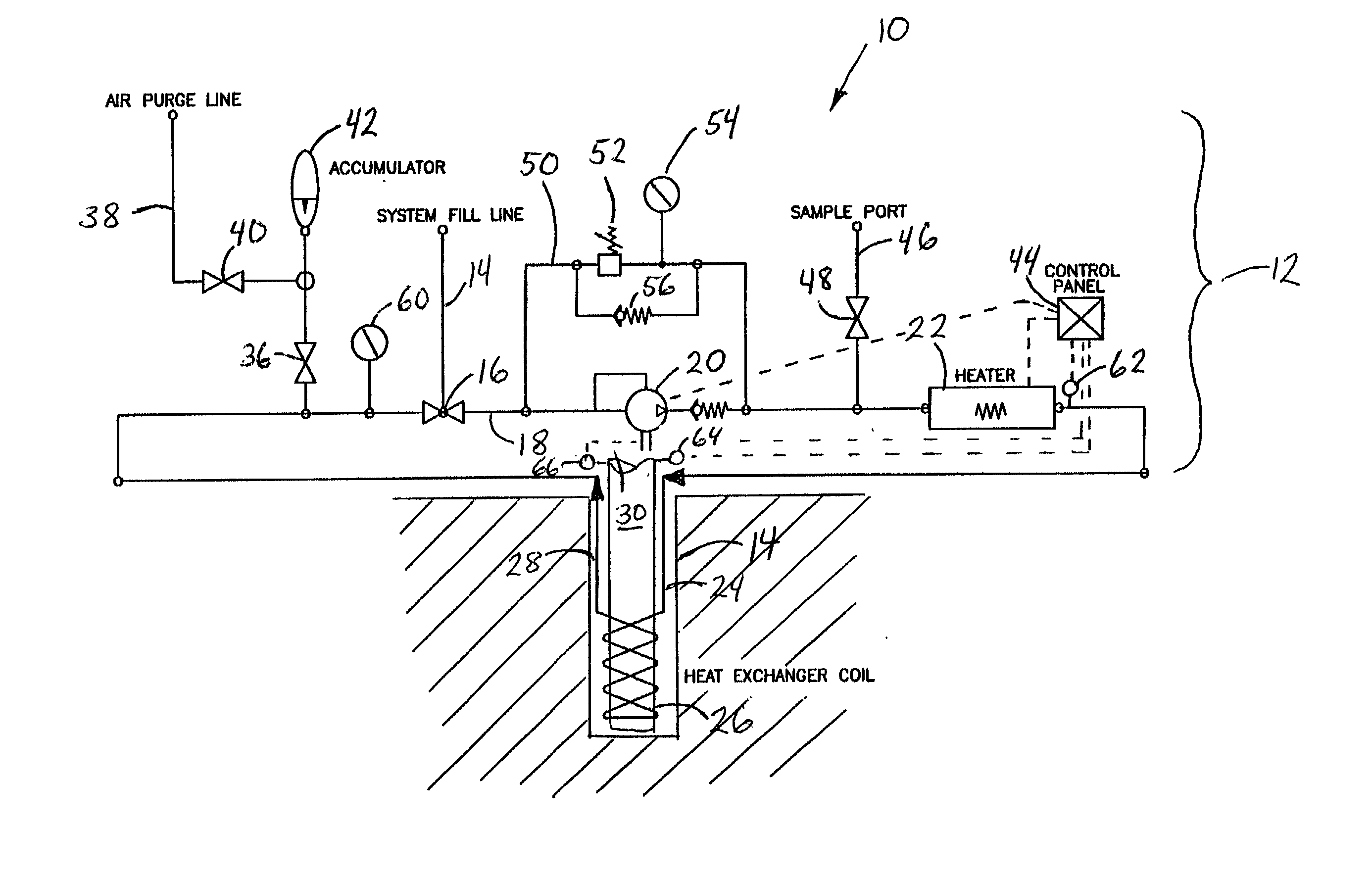
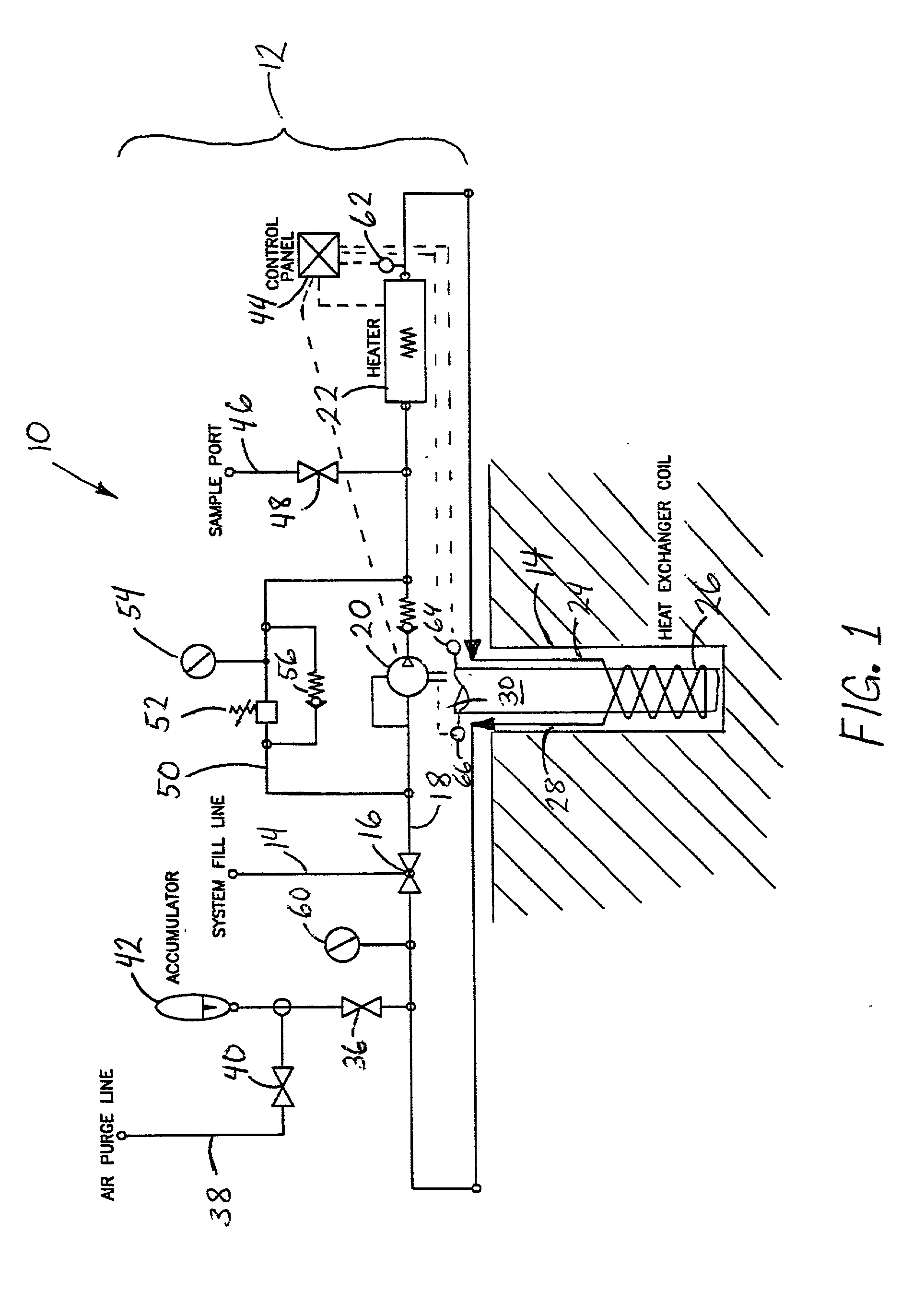
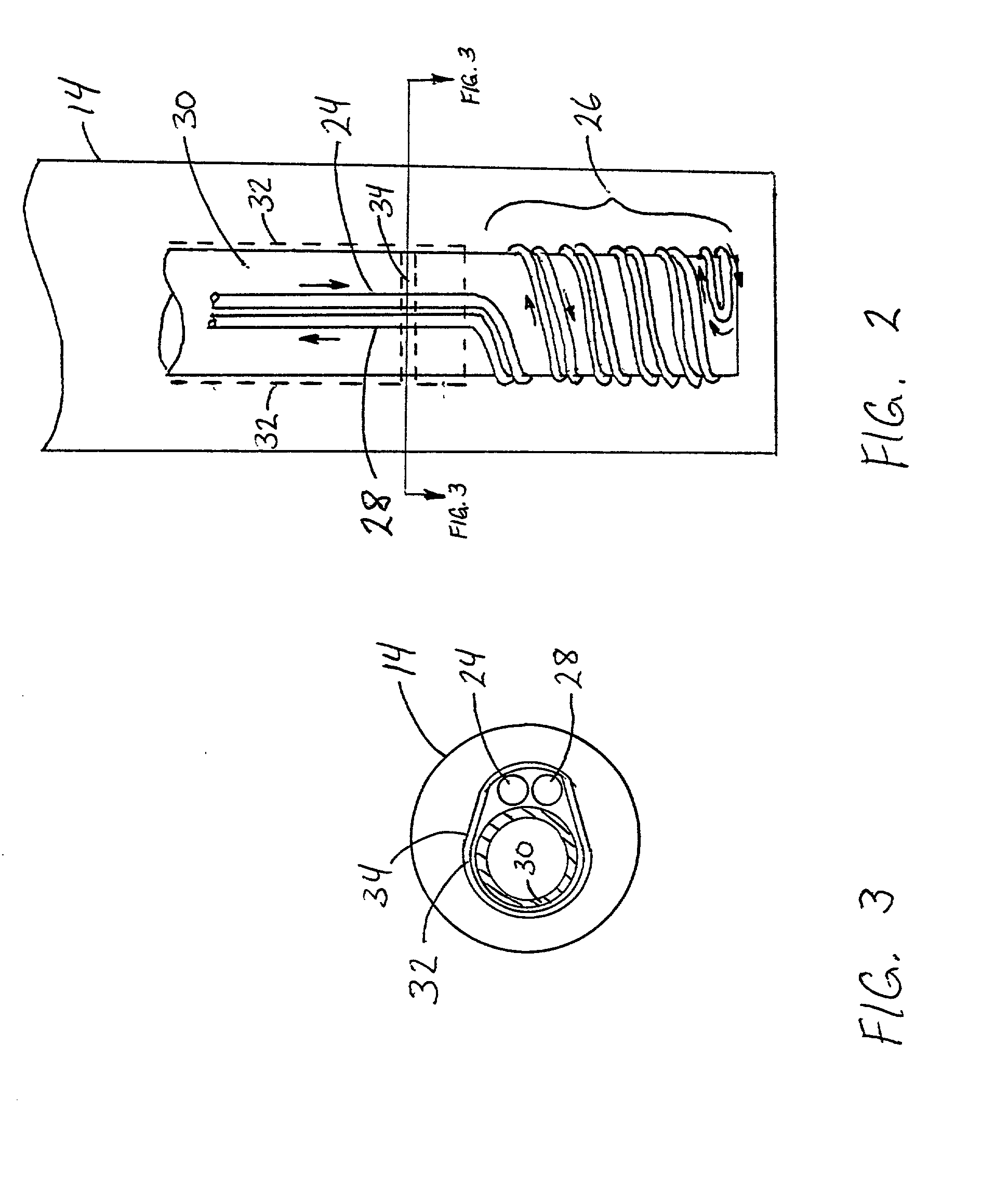
[0014] The present invention provides a system where a fluid specifically designed to be heated to a very high temperature, commonly known as "heat transfer fluid", is placed in a closed loop system that has a heating system located on the surface near the well. The heat transfer fluid is transported from the heating system through supply tubing located in the annulus between the well casing and the outer surface of the production string. The fluid travels through the supply tubing down the length of the production string to a coil submerged in the oil reservoir in the vicinity of the inlet to a production pump. After passing around the pump, the fluid is transported uphole to the wellhead through return tubing located adjacent to the supply tubing. The supply and return tubing are clamped or otherwise secured to the production string so that heat is transferred from the heat transfer fluid to the fluid being produced upward through the production string, as well as the pump and reg...


PUM


Abstract

A closed loop heat transfer system located on the surface near the wellhead for transporting hot fluid through a tubing located in the annulus between the well casing and the outer surface of the production string. The tubing extends down along the production string to a coil submerged in the oil reservoir in the vicinity of the production pump and back to the surface for reheating and recirculation. The tubing provides heat transfer from the hot fluid to the production fluid, as well as the downhole pump and the region of the oil reservoir surrounding the pump. The system is preferably operated to transfer enough heat to the oil to prevent paraffins from coagulating and forming deposits on the production string or sucker rods, if used. The higher temperature lowers the viscosity of the oil and increases oil production.

Description

BACKGROUND OF THE INVENTION[0001] 1. Field of the Invention[0002] The present invention relates to an apparatus and method for the enhanced removal of high viscosity crude oil from downhole formations.[0003] 2. Background of the Related Art[0004] The quick and efficient movement of oil from its natural reservoir or formation, typically located thousands of feet below the earth's surface, to the surface is important to the economically feasibility of producing from a given well. Increasing the temperature of oil that has a high viscosity will make the oil flow more efficiently and thereby possibly increase the amount of oil to be pumped while decreasing the operational expense of removing the oil.[0005] The raising of the temperature of the oil located in the reservoir adjacent to the pump intake will increase the pump's ability to quickly and more effectively move the oil from the reservoir to the production string. This will also increase the oil production rate for the well.[0006]...

Claims


Application Information

Patent Timeline
Patent Type & Authority Applications(United States)
IPC IPC(8): E21B36/00
CPCE21B36/005
Inventor LEWIS, KEN
Owner HAWKEN GORDON GERALD MR
Why Eureka
Try Eureka