Network management system and method of management control in a communication system

Inactive Publication Date: 2002-08-01
GOOGLE TECH HLDG LLC +1
View PDF15 Cites 15 Cited by
  • Summary
  • Abstract
  • Description
  • Claims
  • Application Information

AI Technical Summary

Problems solved by technology

Generally, in distributed telecommunication networks, particularly telecommunication networks used for providing wireless telecommunications (such as the Global System for Mobile communication, GSM), the identification of faults within the network becomes increasingly difficult.
Moreover, with the rapidly growing deployment of infrastructure, and with modern systems operating greater flexibility and dynamism, it is becoming increasingly difficult to manage fault tracking.
In particular, it is difficult to verify the accuracy and authenticity of fault information and to determine from fault information where the problem actually lies.
Anyway, remote identification of faults seldom provides an indication of the underlying cause of such faults and so identification and implementation of appropriate remedial actions is, to say the least, presently difficult.
In a rapidly expanding distributed system, possibly spread across a large geographical region, collecting additional data may require access, either physically or logically, to different network elements or nodes in order to download the extra data required and this is time-consuming and potentially difficult.
Usually, the extent of such change cannot be accurately modelled (e.g. in advance of roll-out of additional equipment), with

Method used


Image

  • Network management system and method of management control in a communication system
  • Network management system and method of management control in a communication system
  • Network management system and method of management control in a communication system

Examples


Embodiment Construction

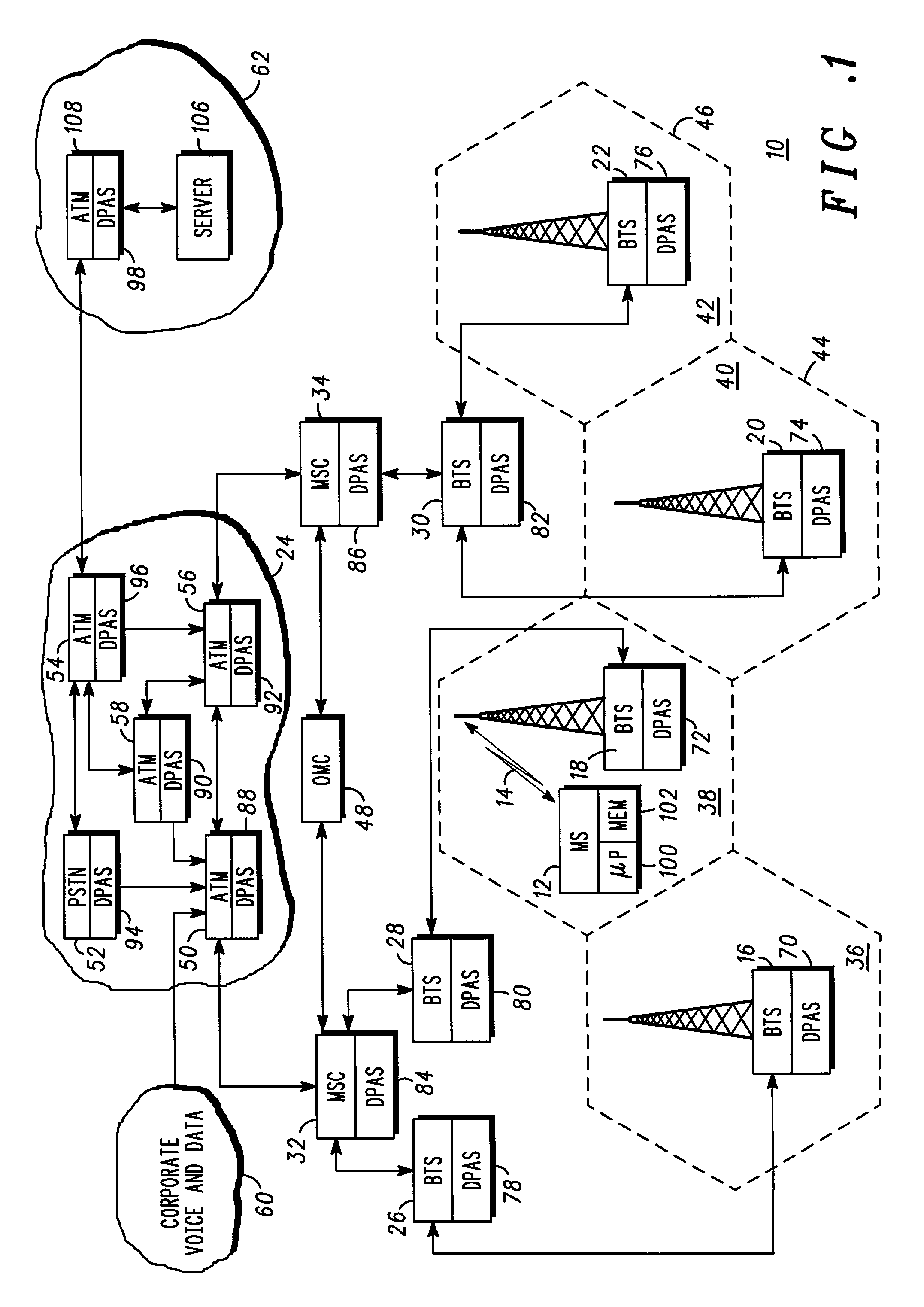
[0036] FIG. 1 shows, in outline, a telecommunication system 10. A mobile station (MS) 12 (of which there are many within each cell of the system) communicates over an air interface 14 with at least one base transceiver station (BTS) 16-22 support a coverage area. Each BTS 16-22 is connected to a telephone network 24 via a base station controller (BSC) 26-30 and a mobile switching centre (MSC) 32-34. BTS are therefore interconnected through MSCs. Each BSC 26-30 is therefore responsible for providing service to at least one cell 36-42 through control of one or more BTSs 16-22, with each cell containing one or more BTSs. The system may support and overlay-underlay environment of cells, as is well known, with a plurality of micro-cells 44-46 controlled by a single BSC. Each MSC may also be connected to an operations and maintenance centre (OMC) 48. The OMC may contain a central time reference, with which clocks in the various other nodes of the network may be synchronised.

[0037] In comb...


PUM


Abstract

A telecommunications network system (10), formed of multiple interconnected nodes (16-22, 26-34, 50-58), is shown in FIG. 1. At least some of the nodes are provided with application spaces (DPASs, 70-94) into which specific programs can be downloaded and run. The application space (DPASs, 70-94), realized by control logic and memory, takes control of managing specific programs and reporting results arising from execution of the specific programs. The application spaces support specific functionality dependent upon the functionality of the node, and support real-time downloading and running of code. Resultant data acquired from running the specific programs is correlated between nodes to produce highly pertinent management data that is communicated to a management device, such as an OMC (48), for analysis and fault identification/performance optimization. Execution of code at specific nodes, followed by shuffling of the code to interconnected nodes, allows operational assessment of successive nodes and interconnecting paths, with correlation of results limiting management data communicated to the management device. Another embodiment provides for the shuffling of test code between nodes, with any inability either to execute code or to generate a predetermined response considered to be indicative of a fault at either that node or at a connection path coupled thereto.

Description

BACKGROUND TO THE INVENTION[0001] This invention relates, in general, to a telecommunication network management system and is particularly, but not exclusively, applicable to cellular-type systems supporting a distributed control arrangement, such as that provided by interconnected base site controllers (BSCs) and operations and management centres (OMCs).SUMMARY OF THE PRIOR ART[0002] Generally, in distributed telecommunication networks, particularly telecommunication networks used for providing wireless telecommunications (such as the Global System for Mobile communication, GSM), the identification of faults within the network becomes increasingly difficult. In such networks, an end-to-end route for a call is not known at call set-up and the call, in any event, may traverse networks owned or managed by several independent operators. Moreover, with the rapidly growing deployment of infrastructure, and with modern systems operating greater flexibility and dynamism, it is becoming inc...

Claims


Application Information

Patent Timeline
IPC IPC(8): H04W24/00
CPCH04W24/00
Inventor THOMAS, HOWARDCHAMBERS, DAVID FRASERBARTLETT, IANCRICHTON, PAUL
Owner GOOGLE TECH HLDG LLC
Why Eureka
Try Eureka