Multi-frequency telescope apparatus for celestial observations using reflecting telescope

a multi-frequency telescope and telescope technology, applied in the direction of instruments, lighting and heating apparatus, optical elements, etc., can solve the problem of uneconomical use of telescopes corresponding to the respective frequencies

Inactive Publication Date: 2002-08-08
MITSUBISHI ELECTRIC CORP
View PDF11 Cites 7 Cited by
  • Summary
  • Abstract
  • Description
  • Claims
  • Application Information

AI Technical Summary

Problems solved by technology

Moreover, observation frequencies of radiotelescopes have recently approached approximately {fraction (1/300)} of frequencies of the visible and infrared rays, and t...

Method used


Image

  • Multi-frequency telescope apparatus for celestial observations using reflecting telescope
  • Multi-frequency telescope apparatus for celestial observations using reflecting telescope
  • Multi-frequency telescope apparatus for celestial observations using reflecting telescope

Examples


embodiment 2

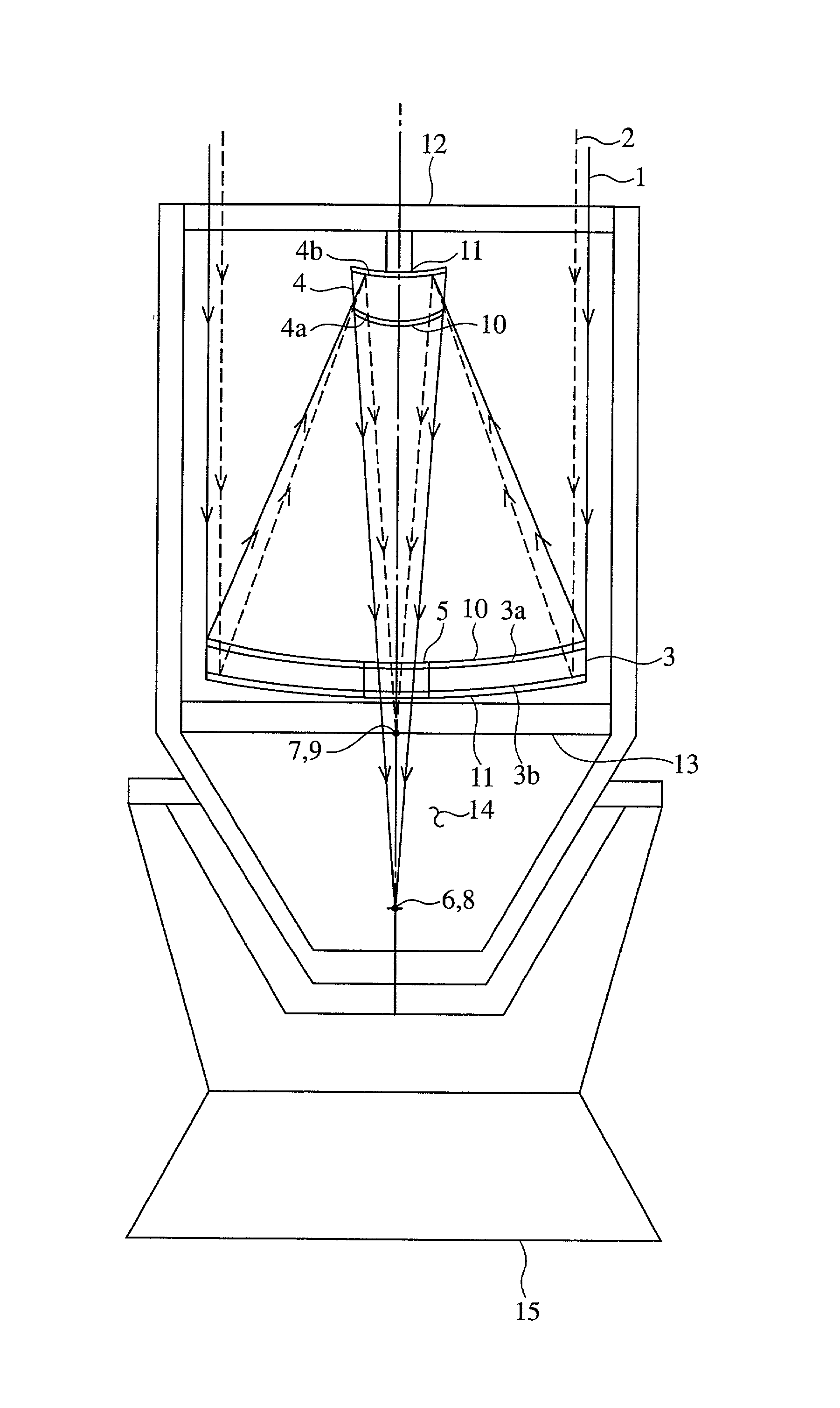
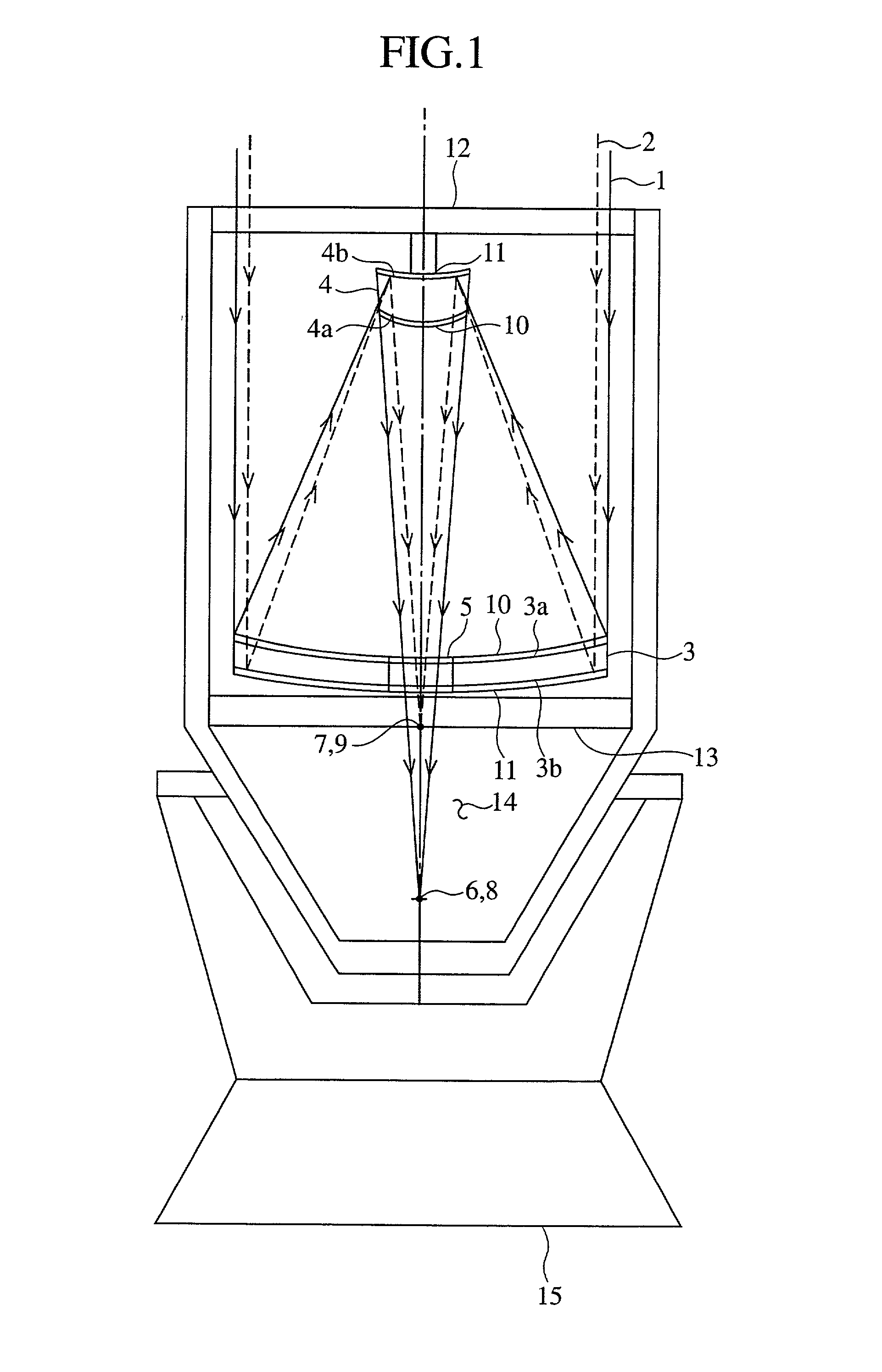
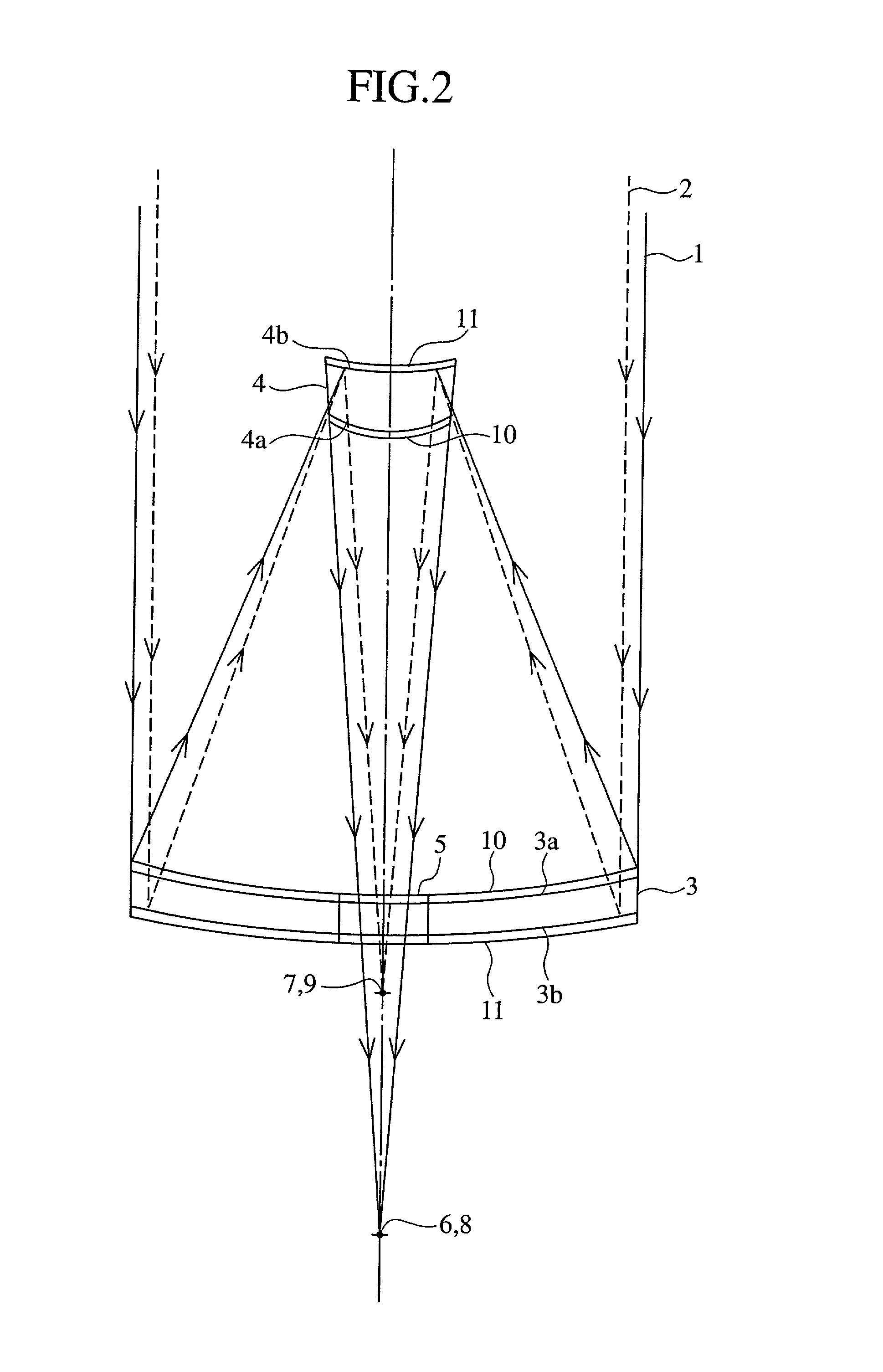
[0040] FIG. 3 is a schematic showing of the optical system of a multi-frequency telescope apparatus for celestial observations using a reflecting telescope according to a second embodiment (Embodiment 2) of the present invention. In FIG. 3, the same parts as those in FIG. 2 are designated by similar reference numerals. Reference numeral 12 denotes a plane mirror disposed just short of the focal point 6; 13 denotes a plane mirror disposed just short of the focal point 7; 6' denotes a focal point newly provided by the placement of the plane mirror 12; and 7' denotes a focal point newly provided by the placement of the plane mirror 13.

[0041] In Embodiment 2, the main reflecting mirror 3 serves as a first reflecting mirror formed by a concave mirror, and the sub reflecting mirror 4 serves as a second reflecting mirror formed by a convex mirror. Accordingly, the optical system of the multi-frequency telescope apparatus of this embodiment is also a Cassegrain optical system.

[0042] While E...

embodiment 3

[0046] FIG. 4 is a schematic showing of the optical system of a multi-frequency telescope apparatus for celestial observations using a reflecting telescope according to a third embodiment (Embodiment 3) of the present invention. In FIG. 4, the same parts as those in FIG. 2 are designated by similar reference numerals, and hence their description will not be repeated. In this embodiment the sub reflecting mirror 4 has the full-face metallic film 11 coated all over its surface 4a but has no metallic film on the back 4b.

[0047] In Embodiment 3 the main reflecting mirror 3 is a concave mirror serving as a first reflecting mirror, and the sub reflecting mirror 4 is a convex mirror serving as a second reflecting mirror. Accordingly, the optical system of the multi-frequency telescope of this embodiment is also a Cassegrain optical system.

[0048] Since this embodiment is identical in construction with Embodiment 1 except that the sub reflecting mirror 4 has the full-face metallic film 11 coa...

embodiment 4

[0052] FIG. 5 is a schematic showing of the optical system of a multi-frequency telescope apparatus for celestial observations using a reflecting telescope according to a forth embodiment (Embodiment 4) of the present invention. In FIG. 5, the same parts as those in FIG. 2 are designated by similar reference numerals, and hence their description will not be repeated. In FIG. 5 the main reflecting mirror 3 has its surface 3a coated with the full-face metallic film 11 but has no metallic film on the back 3b.

[0053] In this embodiment the main reflecting mirror 3 is a concave mirror serving as the second reflecting mirror, and the sub reflecting mirror is a convex mirror serving as the first reflecting mirror. Accordingly, the optical system of the multi-frequency telescope apparatus of this embodiment is also the Cassegrain optical system.

[0054] Since this embodiment is identical in construction with Embodiment 1 except that the main reflecting mirror 3 has the full-face metallic film ...


PUM


Abstract

A telescope apparatus for celestial observations by a reflecting telescope which is provided with: a first reflecting mirror 3 having its surface 3a coated over the entire area thereof with a grid-like metallic film 10 that reflects radio waves 1 but permits the passage therethrough of infrared and visible rays 2 and having its back 3b coated over the entire area thereof with a full-face metallic film that reflects both of the radio waves 1 and the infrared and visible rays 2; and a second reflecting mirror 4 having its surface 4a coated over the entire area thereof with the grid-like metallic film 10 that reflects the radio waves 1 but permits the passage therethrough of the infrared and visible rays 2 and having its back 4b coated over the entire area thereof with the full-face metallic film 11 that reflects both of the radio waves 1 and the infrared and visible rays.

Description

[0001] 1. Field of the Invention[0002] The present invention relates to a multi-frequency telescope apparatus for celestial observations using a reflecting telescope for observing celestial objects which emit radio waves, infrared rays and visible light, such as fixed stars, planets, galaxies, star clusters and gases.[0003] 2. Description of the Prior Art[0004] FIG. 8 is a cross-sectional view of a conventional reflecting optical telescope apparatus of a Cassegrain optical system disclosed, for example, in Japanese Patent Application Laid-Open Gazette No. 05-19179. FIG. 9 is a sectional view of the optical system of the conventional telescope apparatus depicted in FIG. 8. Reference numeral 1 denotes radio waves from celestial objects; 2 denotes infrared and visible rays from the celestial objects; 3 denotes a main reflecting mirror coated over the entire area of its curved glass surface 3a with a thin metallic film 11 as of aluminum (Al); and 4 denotes a sub reflecting mirror coated...

Claims


Application Information

Patent Timeline
IPC IPC(8): G02B17/06H01Q19/19G02B23/02
CPCG02B17/061G02B17/0694
Inventor SUGIYAMA, RYUUICHI
Owner MITSUBISHI ELECTRIC CORP
Why Eureka
Try Eureka