Self-oscillating electronic discharge lamp ballast with dimming control

Inactive Publication Date: 2002-08-22
VIRGINIA TECH INTPROP INC
View PDF0 Cites 25 Cited by
  • Summary
  • Abstract
  • Description
  • Claims
  • Application Information

AI Technical Summary

Problems solved by technology

However, some problems have been presented in the past in regard to light spectral content and the ability to control the amount of light output from a given gas-discharge lamp which are not presented by incandescent light sources.
However, the electrical characteristics of gas-discharge lamps are much more complicated than those of incandescent lamps (the latter being essentially a slightly variable resistor) and known arrangements for controlling light output of gas-discharge lamps have been correspondingly complex and expensive.
Unfortunately, as alluded to above, electronic ballast providing for dimming control is expensive and complex.
However,

Method used


Image

  • Self-oscillating electronic discharge lamp ballast with dimming control
  • Self-oscillating electronic discharge lamp ballast with dimming control
  • Self-oscillating electronic discharge lamp ballast with dimming control

Examples


Embodiment Construction

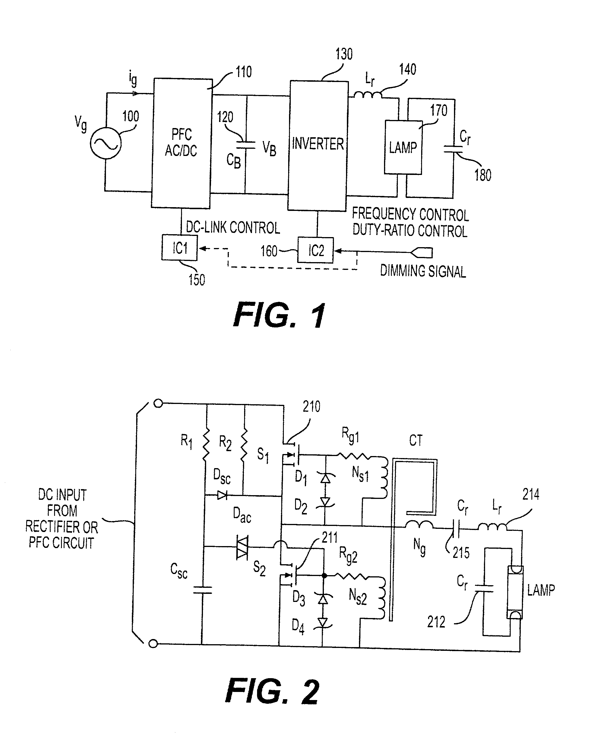
[0025] Referring now to the drawings, and more particularly to FIG. 1, there is schematically shown a generalized electronic ballast including a dimming system including functional blocks common to such arrangements known in the art and currently available. Since this depiction is generalized and arranged to facilitate an understanding of the invention, no portion of FIG. 1 (or any other Figure) is admitted to be prior art as to the present invention.

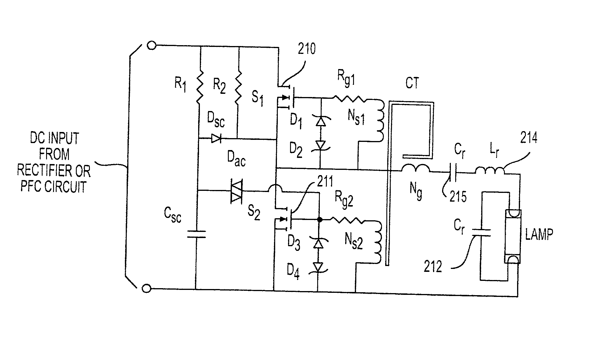
[0026] As shown in FIG. 1, it will often be desirable for the electronic ballast to be powered from an alternating utility line as depicted by alternating voltage source 100. However, the electronic ballast or power supply circuit is preferably powered by direct current. In such a case, it will also often be necessary (e.g. to comply with IEC-61000-3-2 class C regulations) to include power factor correction and AC / DC conversion 110. It is to be understood that such arrangements are generally well-understood in the art and, while omitted...


PUM


Abstract

A simplified electronic ballast for a discharge lamp which provides dimming by control of inverter frequency through modulation of magnetizing current in a transformer such that the switching frequency is made substantially independent of the load presented. The principle of frequency control in a manner independent of the load is extendable to other types of loads and power supplies and converters to regulate power coupled to the load. Clamping capacitors are used to replace other clamping circuits in order to allow current injection to be controlled by a simple variable voltage while frequency control by current injection provides enhanced circuit performance.

Description

[0001] 1. Field of the Invention[0002] The present invention generally relates to self-oscillating power supplies with adjustable power control and, more particularly, to electronic, self-oscillating discharge lamp ballast with lamp dimming control.[0003] 2. Description of the Prior Art[0004] The increased efficiency of gas-discharge lamps, such as well-known fluorescent tubes, over incandescent light sources has long been appreciated. Such gas-discharge light sources generally produce far less heat and thus have a much higher efficiency of energy conversion to light. Overall efficiency of such lamps in a given application may also be increased by the fact that removal of heat is generally unnecessary. However, some problems have been presented in the past in regard to light spectral content and the ability to control the amount of light output from a given gas-discharge lamp which are not presented by incandescent light sources.[0005] Nevertheless, the efficiency gains to be realiz...

Claims


Application Information

Patent Timeline
IPC IPC(8): H05B41/282H05B41/392
CPCH05B41/2827H05B41/3925Y02B20/185Y02B20/00
Inventor TAO, FENGFENGLEE, FRED C.
Owner VIRGINIA TECH INTPROP INC
Why Eureka
Try Eureka