
Master cylinder for use in power trains of motor vehicles

a technology for motor vehicles and master cylinders, applied in the direction of rotary clutches, fluid couplings, brake systems, etc., can solve the problems of generating easily detectable noise, generating often highly pronounced and highly unpleasant screeching, creaking or squealing noises,

Inactive Publication Date: 2002-08-29
LUK LAMELLEN & KUPPLUNGSBAU BETEILIGUNGS KG
View PDF0 Cites 60 Cited by
  • Summary
  • Abstract
  • Description
  • Claims
  • Application Information

AI Technical Summary

Benefits of technology

[0010] An object of the invention is to provide a single or dual master cylinder which is constructed and assembled in such a way that movements of its piston(s) relative to the housing(s) are less likely to generate pronounced noise (or any noise) than the movements of the piston(s) in conventional master cylinders for use in the power trains of motor vehicles.
[0011] Another object of the invention is to provide a master cylinder the operation of which is satisfactory (such as without the generation of any noise or any appreciable noise) during the entire useful life of the master cylinder and / or of the power train in which the master cylinder is put to use.
[0012] A further object of the invention is to provide a master cylinder which is constructed and assembled in such a way that it prevents the transmission of undesirable stray movements from one or more controlled parts (such as a slave cylinder) to the part or parts (such as a pedal or an actuator) serving to actuate the master cylinder.

Problems solved by technology

A drawback of such master cylinders is that each actuation can involve, or is likely to involve, the generation of often highly pronounced and highly unpleasant screeching, creaking or squealing noises attributable to the absence of any or adequate films of lubricant between the parts (such as the piston and the sealing rings) which must move relative to each other in response to depression of the brake pedal or clutch pedal.
Thus, the adhesion between the surface of the piston and the surface(s) of one or more sealing elements is likely to be sufficiently pronounced to cause the generation of readily detectable noise whenever the operator of the motor vehicle decides to move the piston relative to the housing of the master cylinder or when such decision is rendered by the electronic control unit and effected by the actuator of the prime mover in the motor vehicle.
It has been ascertained that a master cylinder is likely to generate noise regardless of whether its piston is made of steel, aluminum or a plastic material with or without a metallic or plastic jacket.
The generation of noise is attributable to the development of oscillations which can or are likely to be sufficiently pronounced to constitute a cause of discomfort to the operator and other occupant(s) of the motor vehicle.
Attempts to overcome such drawbacks of presently known master cylinders by utilizing special lubricants have met with limited success, partly or mainly because it is difficult or impossible to ensure adequate lubrication during the entire useful life of the master cylinder and / or of the arrangement (such as the brake system or the clutch) which is connected with and is actuated by the master cylinder.
Another drawback of many presently known master cylinders is that they are likely to be vibrated by the parts which receive pressurized fluid from the plenum chamber of the housing.
For example, if the master cylinder is installed to actuate the disengaging unit (such as a slave cylinder) for a friction clutch in the power train of a motor vehicle, vibrations of the slave cylinder (such vibrations are normally attributable to vibrations of the internal combustion engine in the power train) are a cause of pulsating changes of fluid pressure in the conduit connecting the slave cylinder with the chamber in the housing of the master cylinder.
The just discussed oscillations of the piston rod are a cause of discomfort and / or uncertainty to the operator of the motor vehicle and / or a cause of undesirable stressing of the actuator for the clutch.

Method used


Image

  • Master cylinder for use in power trains of motor vehicles
  • Master cylinder for use in power trains of motor vehicles
  • Master cylinder for use in power trains of motor vehicles

Examples


Embodiment Construction

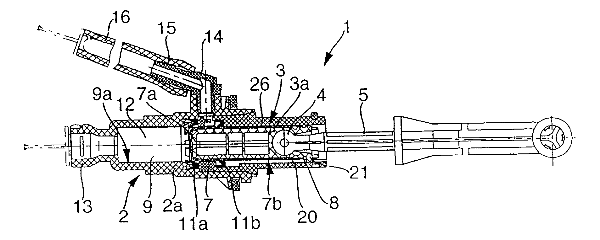
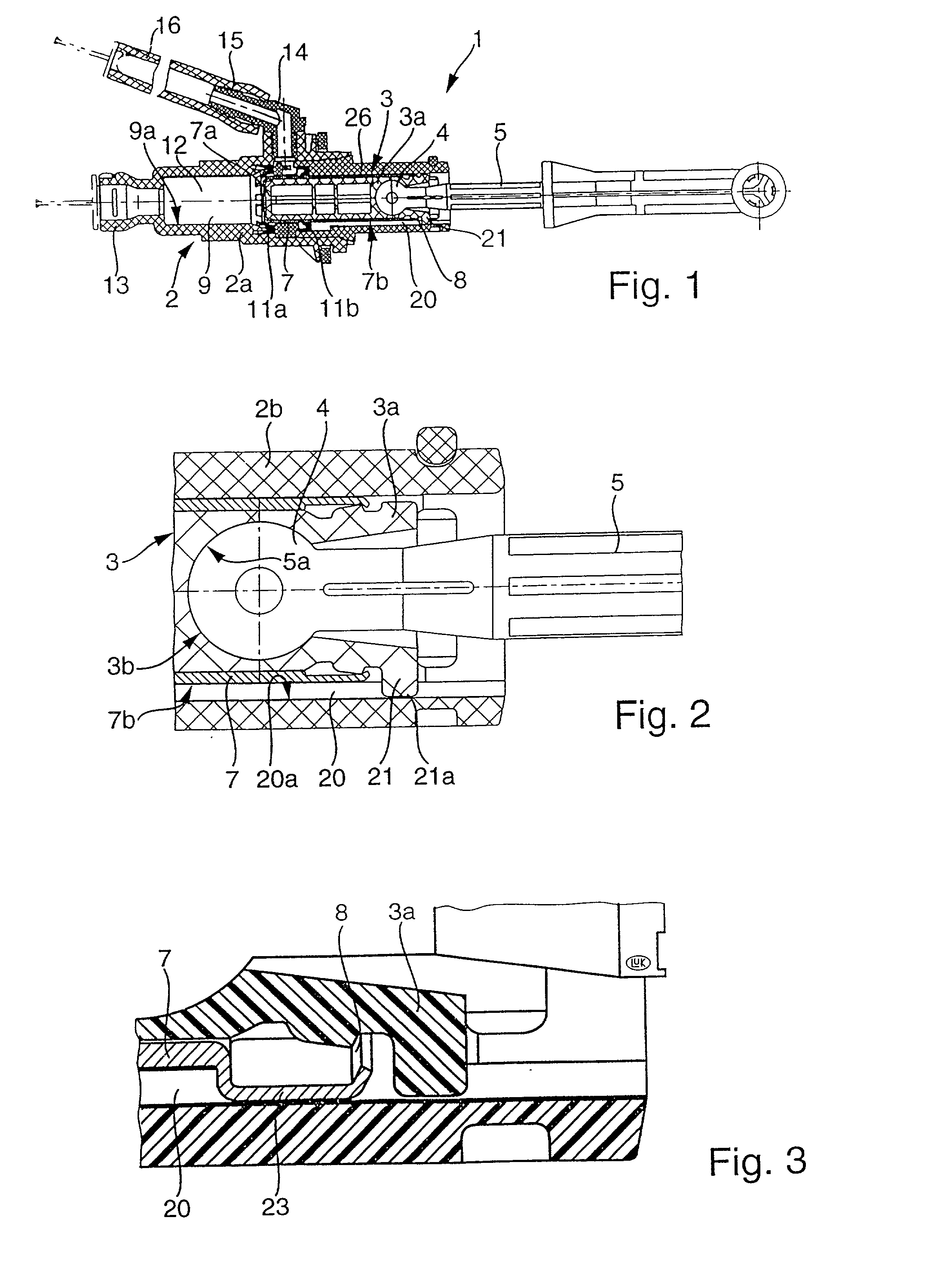
[0072] The master cylinder 1 of FIG. 1 comprises an elongated cylindrical housing 2, an elongated piston 3 which is reciprocable in the housing 2 and defines therewith a plenum chamber 12 for a supply of hydraulic fluid, and means for moving the piston 3 axially of the cylinder 2. The means for moving comprises a piston rod or push rod 5 and means 4 for articulately connecting the piston rod 5 with that end portion of the piston 3 which is remote from the chamber 12.

[0073] The piston 3 comprises a core or body 3a and a jacket or shell 7 which surrounds at least a major part of the core. The housing 2 comprises a front portion or section 2a which surrounds the chamber 12, and a rear portion or section 2b which is or which can be of one piece with the section 2a and serves to guide the jacket 7 of the piston 3 for axial movement between a retracted position (coinciding with or close to that shown in FIG. 1) and an extended position close to a nipple 13 at the front end of the section ...


PUM


Abstract

A master cylinder for use in the power train of a motor vehicle to actuate the brakes or the friction clutch is designed to avoid the generation of screeching noise and / or the transmission of stray movements to the piston rod in response to shifting of the piston relative to the housing and relative to the sealing element(s) between the piston and the housing. This can be accomplished by causing the piston to turn relative to the housing and the sealing element(s) during axial movement in the housing and / or by installing one or more dampers between the piston and the housing and / or between the piston and the piston rod. The dampers can constitute separately produced parts and / or specially configured and / or finished surfaces provided on the piston and contacting the housing and / or the sealing element(s). The invention also relates to improvements in the configuration and / or the material(s) of the piston.

Description

CROSS-REFERENCE TO RELATED CASES[0001] This application is a division of application Ser. No. 09 / 690,428 filed Oct. 17, 2000.[0002] The disclosure of the commonly owned pending German priority application Ser. No. 199 50 082.7 (filed Oct. 18, 1999), as well as of each U.S. and foreign patent and patent application identified in the specification of the present application, is incorporated herein by reference.[0003] This invention relates to pumps in general, and more particularly to improvements in hydraulic pumps of the type known as master cylinders. Such master cylinders are utilized in many types of motor vehicles to actuate clutches and / or brakes.[0004] A master cylinder normally comprises a cylindrical housing, a piston which is reciprocable in and defines with the housing a plenum chamber for a supply of hydraulic fluid, a piston rod or push rod which can receive motion from a pedal or from an actuator to shift the piston from a retracted position to an extended position and ...

Claims


Application Information

Patent Timeline
Patent Type & Authority Applications(United States)
IPC IPC(8): B60T11/16B60T11/18B60T11/236F15B15/14F16D25/08F16D25/12
CPCB60T11/165B60T11/18F15B15/1447F16D25/088F16D25/12F16D2025/081F16D25/08
Inventor WINKELMANN, LUDWIGVENZ, RAINERHELFMEIER, ULRICHADLER, DIETERSTRATIL, UWEBERTELSHOFER, THOMASGRELL, KARL-LUDWIGPESCHKE, HARALDWELTER, ROLAND
Owner LUK LAMELLEN & KUPPLUNGSBAU BETEILIGUNGS KG
Learn More