Clock duty cycle control circuit

a control circuit and duty cycle technology, applied in pulse manipulation, pulse duration/width modulation, pulse technique, etc., can solve the problems of increasing the stability of the duty cycle at the loss of speed, requiring great modification, and sometimes failing in a slightly abnormal environment. , to achieve the effect of reducing the variation of the duty cycl

Inactive Publication Date: 2002-09-12
CHEN PI FEN +1
View PDF0 Cites 41 Cited by
  • Summary
  • Abstract
  • Description
  • Claims
  • Application Information

AI Technical Summary

Benefits of technology

0009] The other purpose of the present invention is to provide a duty cycle control circuit adaptable for an open-drain driver with open-drain output. The variance of the duty cycle is reduced by properly biasing the output path which combines the duty-cycle adjustment circuit and the open-drain-driver.
0010] The duty cycle control circuit according to the present invention includes a circuit for generating a reference voltage, and a constant current generator connected to the reference voltage of the reference voltage generating circuit to provide a bias voltage. In usual, a band-gap reference circuit is used to generate a reference voltage of the present invention. A duty-cycle adjustment circuit is controlled by the bias voltage of the constant current generator, and adjusts the clock signal. Accordingly, the bias voltage controls the duty-cycle adjustment circuit so that charging and discharging time therein are under proper control. Finally, an open-drain driver with open-drain output is connected to the duty-cycl

Problems solved by technology

Accordingly, conventional digital electronic system sometimes functions incorrectly or even fails in a slightly abnormal environment, or needs great modification when adapting a disparate fabricating technique.
Nevertheless, such method increases the stabili

Method used


Image

  • Clock duty cycle control circuit
  • Clock duty cycle control circuit
  • Clock duty cycle control circuit

Examples


Embodiment Construction

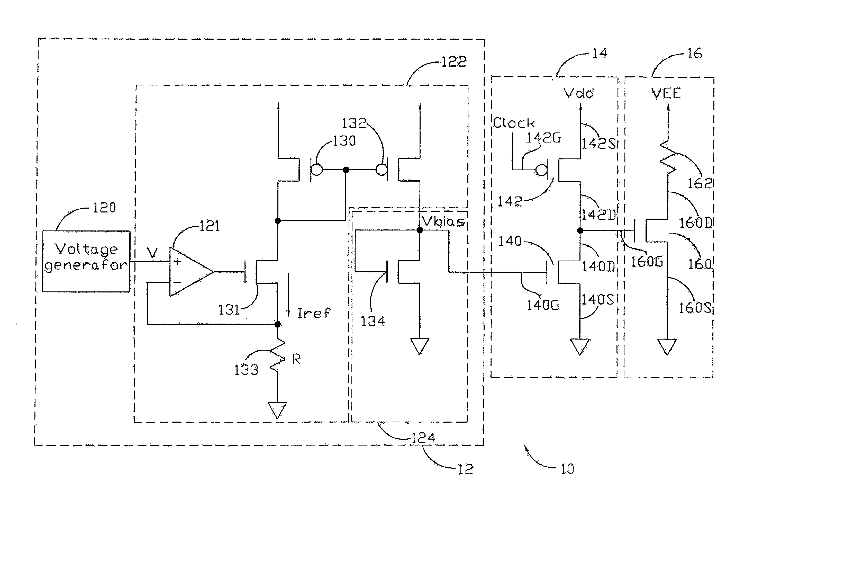
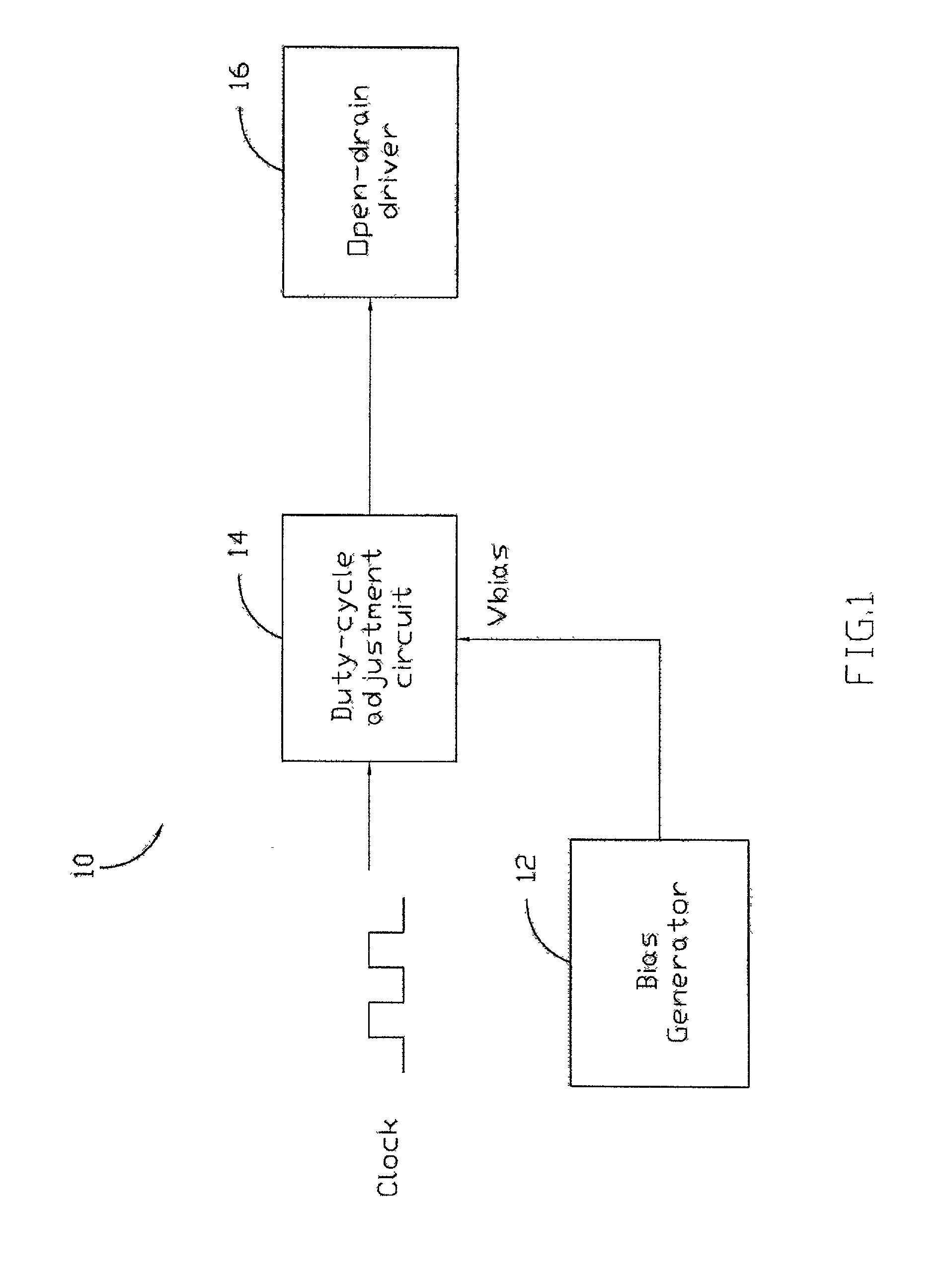
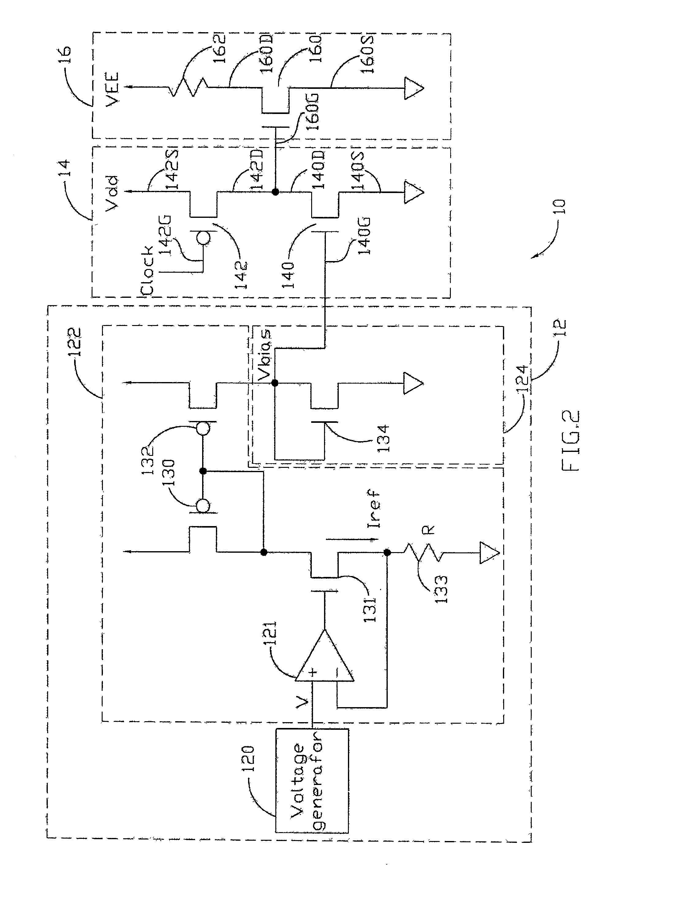
[0014] FIG. 1 shows a schematic diagram illustrating a clock duty cycle control circuit 10 according to one embodiment of the present invention. A bias generator 12 can generate and feed a bias voltage V.sub.bias as to a duty-cycle adjustment circuit 14. By feeding the bias voltage, the charging time and discharging time of the duty-cycle adjustment circuit 14 are controlled so well that they can automatically adjust according to variations of parameters in process or outside environment. Furthermore, the duty-cycle adjustment circuit 14 has input configured to receive a clock signal named as Clock and an output connected to an open-drain driver 16.

[0015] The bias voltage V.sub.bias of the bias generator 12, which is designed to automatically coordinate with the duty-cycle adjustment circuit 14 and the open-drain driver 16, can compensate variances of parameters in process, temperature and voltage, and further generate the clock output of a stable duty cycle (not shown). In particul...


PUM


Abstract

A clock duty cycle control circuit comprises a reference voltage circuit and a constant current generator connected to the reference voltage circuit. A duty-cycle adjustment circuit is used to receive a clock signal and controlled by the bias voltage of the bias voltage generating circuit which is connected to constant current generator. Accordingly, by a method of controlling duty-cycle adjustment circuit, the bias voltage has capability for adjusting a charging time and a discharging time of the clock signal. Finally, an open-drain driver with open-drain output is connected to the duty-cycle adjustment circuit, and thereby substantially stabilizing the output duty cycle of the clock signal.

Description

[0001] This application is a continuation-in-part of U.S. patent application Ser. No. 09 / 695,902, filed Oct. 26, 2000.BACKGROUND OF THE INVENTION[0002] 1. Field of the Invention[0003] The present invention relates to a clock generator, and more particularly, to a duty cycle control circuit with open-drain output.[0004] 2. Description of the Prior Art[0005] A clock generator is conventionally used in a digital electronic system to synchronize the operations or processes performed therein. However, the stability of duty cycle (i.e., the percentage of its active duration over a complete cycle) largely depends on process variation, different internal supply voltage, and / or temperature variation. Accordingly, conventional digital electronic system sometimes functions incorrectly or even fails in a slightly abnormal environment, or needs great modification when adapting a disparate fabricating technique.[0006] In order to overcome the aforementioned problem, separate circuit was proposed ...

Claims


Application Information

Patent Timeline
IPC IPC(8): H03K5/156
CPCH03K5/1565
Inventor CHEN, PI-FENCHEN, CHI-MING
Owner CHEN PI FEN
Why Eureka
Try Eureka