

Piezoelectric siren driver circuit
- Summary
- Abstract
- Description
- Claims
- Application Information
AI Technical Summary
Benefits of technology
Problems solved by technology
Method used
Image

Examples
Embodiment Construction
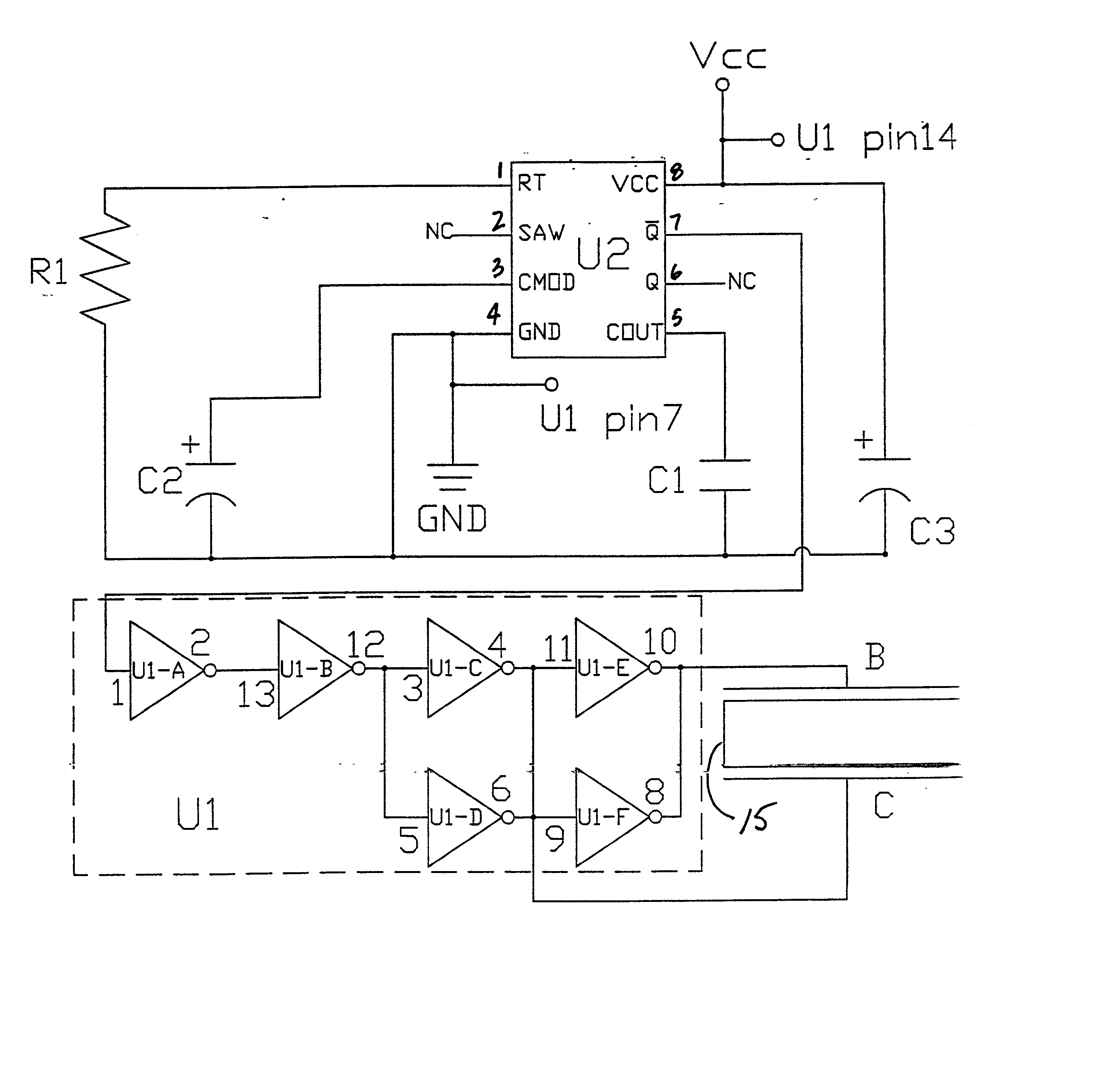
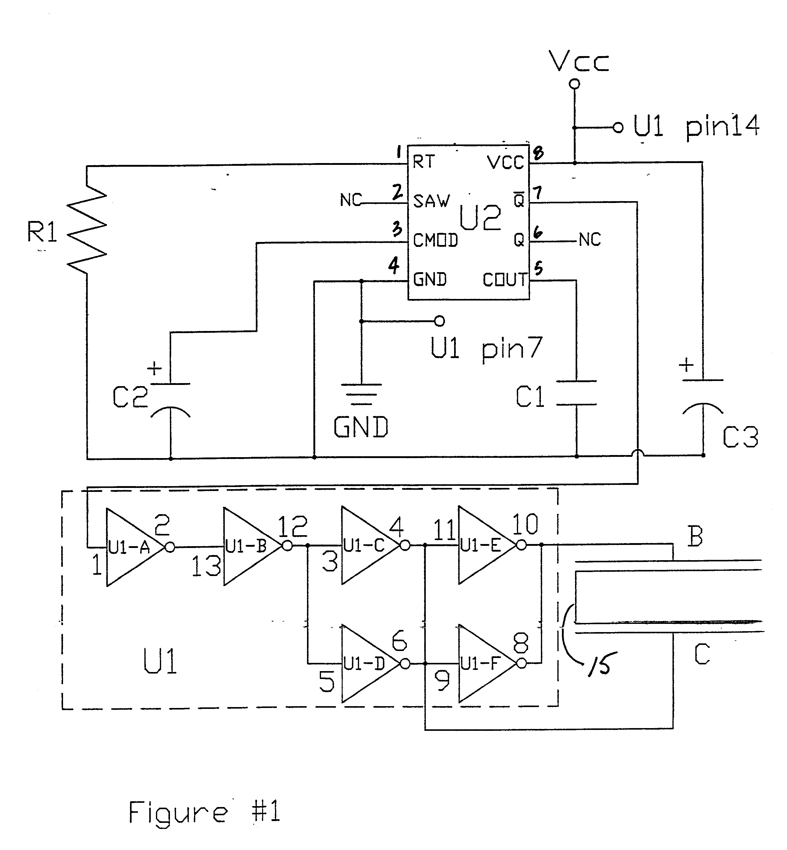
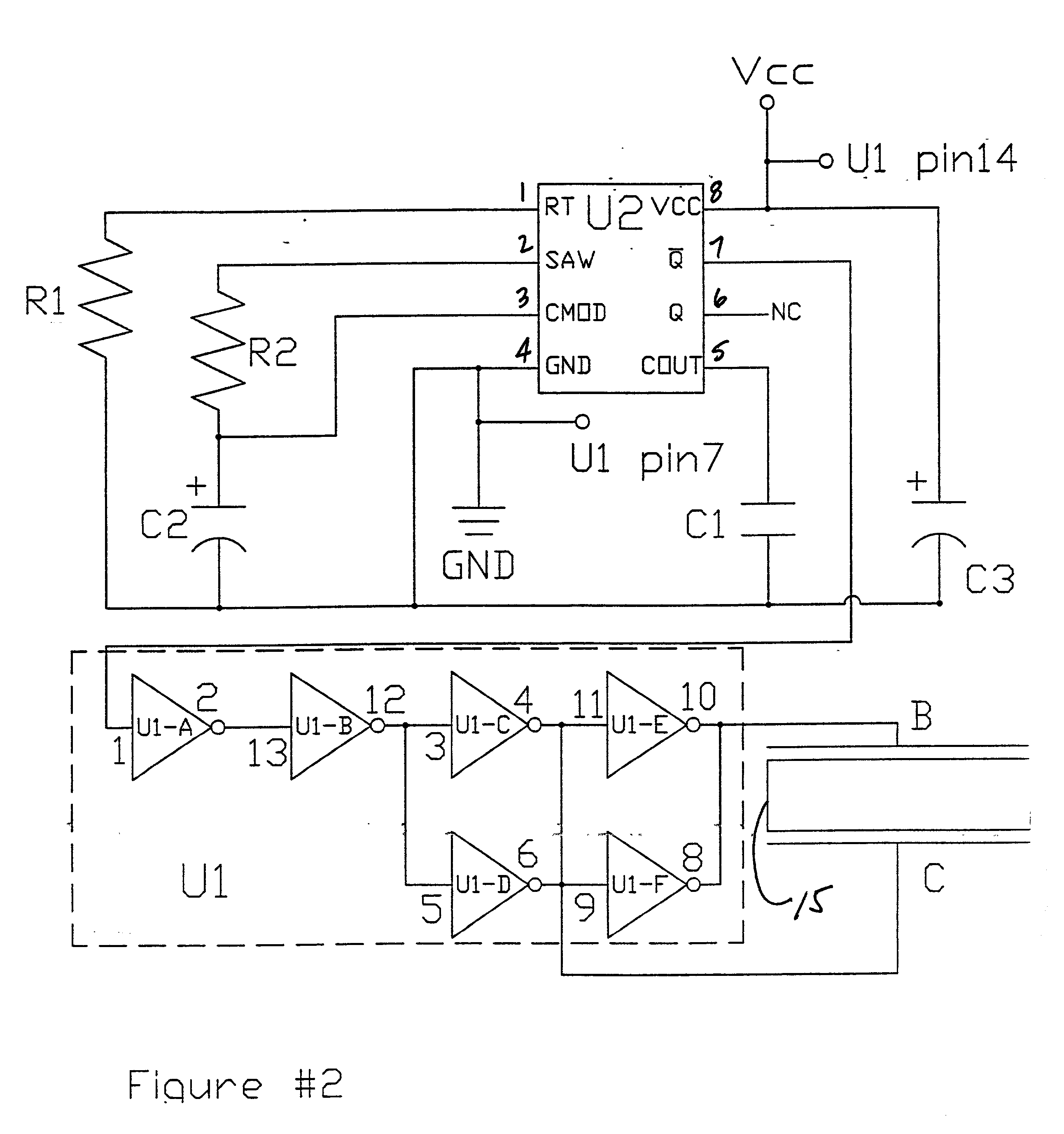
[0024] The piezoelectric siren driver circuit of FIGS. 1 or 2 uses a frequency swept signal generator integrated circuit U2, such as the ZSD100 provided by Zetex Inc. 87 Modular Avenue, Commack, N.Y. 11725, to produce varying output waveforms. As shown in FIG. 11, the manufacturer of the ZSD100 shows a traditional means for driving a piezo sounder. As the manufacturer indicates, the the ZSD100 uses a large power transistor, the ZTX605, to power a transformer T1 which then drives a piezo sounder.
[0025] There are several problems with using a transformer or other inductive components to drive a piezoelectric transducer. A transformer requires a large amount of space, demands large amounts of electrical power, produces electromechanical noise into surrounding components, and is quite expensive. The invention is circuitry that drives a piezoelectric transducer from a device, such as the ZSD 100, with a circuit that is cost effective, small in size, avoids a transformer, and which does n...
PUM
 Abstract
Description
Claims
Application Information