Line probe signal and method of use

a line probe and signal technology, applied in the field of communication, can solve the problems of inconvenient use, inconvenient use, and large time consumption of line evaluation methods, and achieve the effects of good autocorrelation properties, accurate and complete impulse response, and good autocorrelation properties

Inactive Publication Date: 2002-09-12
CHEMTRON RES
View PDF0 Cites 41 Cited by
  • Summary
  • Abstract
  • Description
  • Claims
  • Application Information

AI Technical Summary

Benefits of technology

0013] One embodiment of the invention comprises generation and/or use of sequence signals for line probing. The inventors discovered that sequence signals provide advantages for use as line probe signals as compared to prior art signals, methods, or apparatus used for line probing. One example type of sequence signal comprises a signal with good autocorrelation properties. Good autocorrelation properties provide the advantage during processing of approximation to an impulse signal to thereby estima

Problems solved by technology

While these methods are often implemented in prior art devices, they are plagued by several drawbacks.
One drawback is that these methods of line evaluation are very time consuming.
Each reiteration takes a certain amount of time and hence an undesirably large period of time is consumed when numerous reiterations are performed.
In the particular case of the BER method, the time required to compute the BER can be quite lengthy.
As a result, a new communication technology designed to speed the rate of communication may appear to the user to take longer to configure and initiate operation than the prior `slower` technology.
Another drawback of prior art methods is that because of their hunt-and-peck type operation, the line characterization may be

Method used


Image

  • Line probe signal and method of use
  • Line probe signal and method of use
  • Line probe signal and method of use

Examples


Embodiment Construction

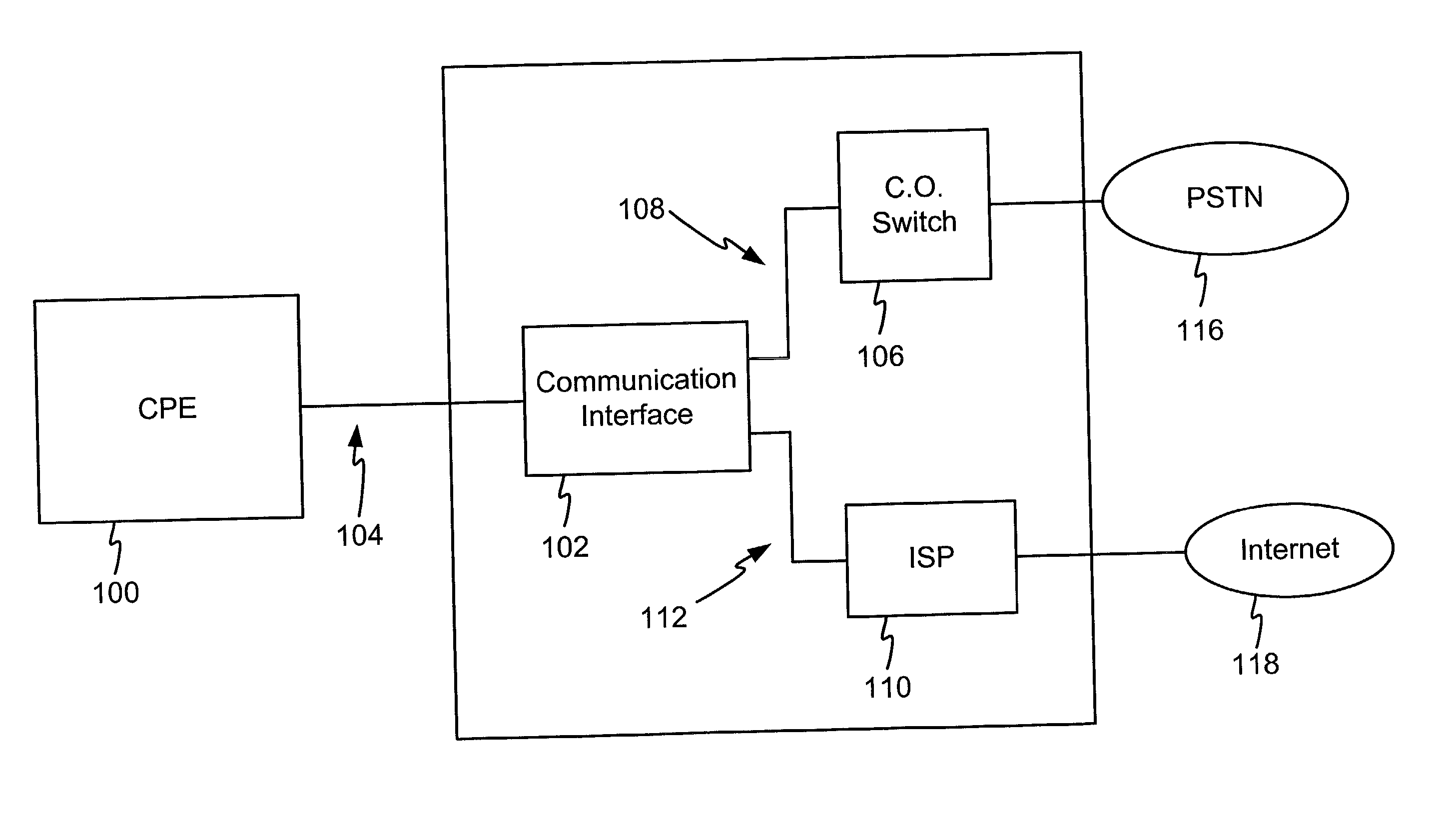
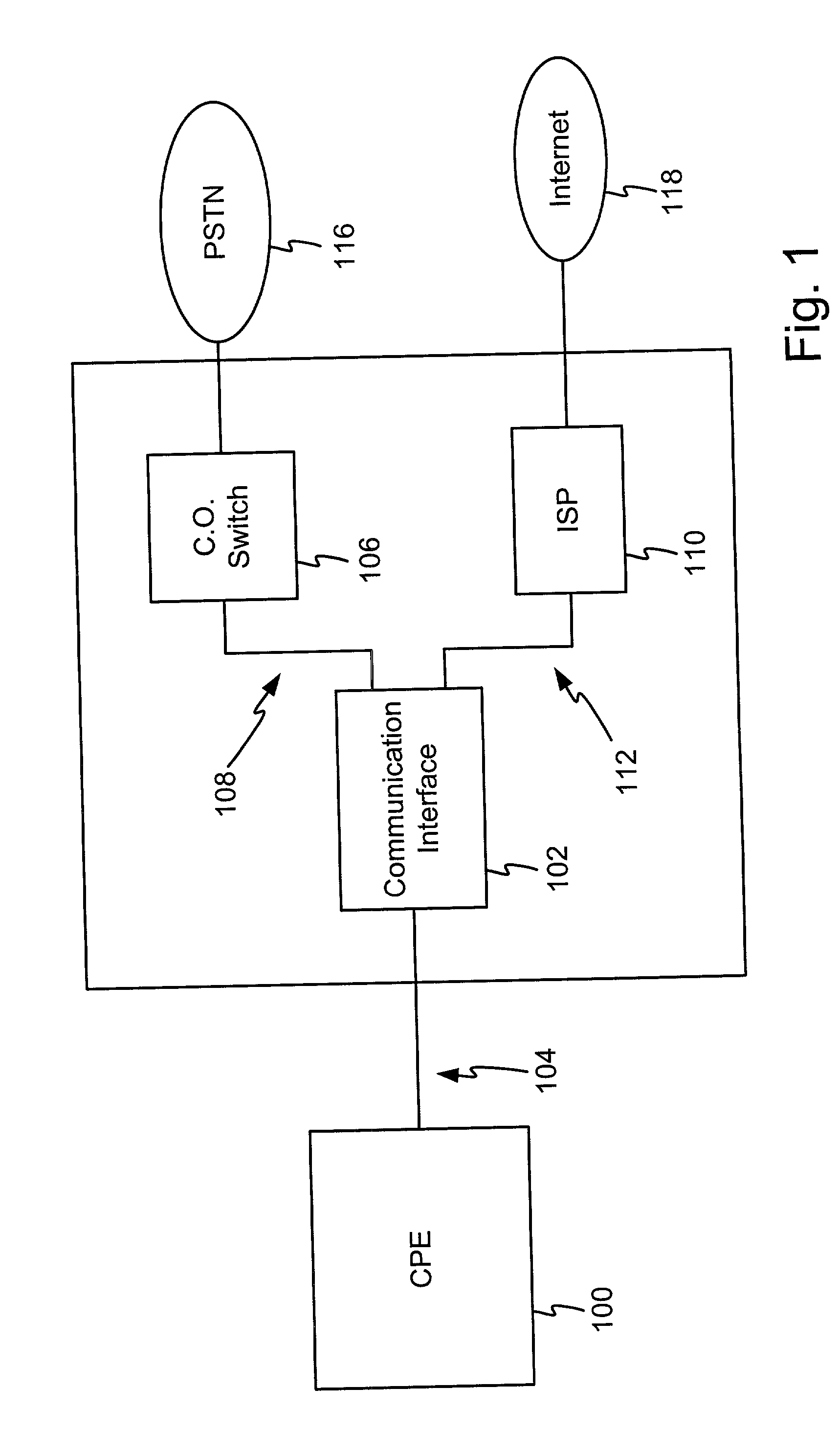
[0034] In one embodiment the invention provides an alternate class or type of signal to use for line probing that overcomes the drawbacks of the prior art. FIG. 1 illustrates an example environment for use of the invention. The example environment shown in FIG. 1 is provided for purposes of discussion and is not in any way intended to limit the scope or breadth of the invention. It is contemplated that the invention find use in a plurality of other environments, such as any environment where it is desired to obtain information regarding line characteristics for the purposes of communication over the line. The line to be probed may comprise any type of conductor or channel including a twisted pair conductor, a wireless channel or an optic channel.

[0035] FIG. 1 illustrates customer premise equipment (CPE) 100 in communication with a communication interface 102 over a first line 104. The CPE 100 comprises any communication device that is generally located remote from the communication ...


PUM


Abstract

A system, method, and signal are disclosed for line probing. The invention provides an improved signal for line probing having desirable characteristics. In various embodiments the signal comprises a periodic sequence having good autocorrelation characteristics. The periodic sequence of the invention provides a faster and more accurate evaluation of the channel. Another embodiment of the invention comprises processing of the received sequence to determine a desired or maximum data rate for the line or channel. The invention also provides an evaluation and calculation of the noise on the line or channel.

Description

BACKGROUND OF THE INVENTION[0001] 1. Technical Field[0002] This invention relates generally to communications and in particular to a system and method for line probing and provisioning.[0003] 2. Related Art[0004] Historically, new communication technologies are continually being introduced to improve the ease and rate at which data can be exchanged between remote locations. One factor that must be considered when communicating electronic data is the medium over which the data will travel. This is often referred to as determining the channel quality, line characteristics, line transfer function, insertion loss, or channel impulse response. One example medium that is commonly installed throughout the world is twisted pair conductors as were traditionally used to provide telephone service between a central office telephone facility and a residence or business.[0005] The medium must be considered because the medium can affect the rate at which communication may occur. For example, digit...

Claims


Application Information

Patent Timeline
IPC IPC(8): H04L1/00H04L5/02H04L5/14H04M1/24H04M3/30
CPCH04L1/0002H04L5/023H04L5/1446H04M1/24H04M3/305
Inventor JONES, WILLIAM W.PATRAVALI, SHRENIKJONSSON, RAGNAR H.OLAFSSON, SVERRIR
Owner CHEMTRON RES
Why Eureka
Try Eureka