
Image processing apparatus

Inactive Publication Date: 2002-09-12
FUJITSU LTD
View PDF0 Cites 61 Cited by
  • Summary
  • Abstract
  • Description
  • Claims
  • Application Information

AI Technical Summary

Benefits of technology

[0020] In view of the above-described problems existing in the prior art, the main object of the present invention is to provide an image processing apparatus which allows one or a plurality of objects to be rapidly and accurately extracted and analyzed, in a case where a large number of moving objects exist in a time series image.
[0022] A still further object of the present invention is to provide an image processing apparatus which allows the movement of each of a plurality of moving objects to be rapidly and accurately extracted and analyzed, even in the case where the plurality of moving objects respectively move with different speeds.

Problems solved by technology

More specifically, if a plurality of objects respectively existing in a plurality of the time series images are not accurately correlated with each other, by analyzing all the areas where the object can exist, it is difficult to calculate the speed of the object with a sufficiently high accuracy.
However, especially in the case where a large number of moving objects exist in one image, a process for correlating a plurality of objects in the time series images with each other for all the moving objects becomes difficult.
Further, when a plurality of stationary objects exist, as well as a plurality of moving objects, it becomes extremely difficult to rapidly complete such a correlation process for all of the stationary and moving objects using real time processing with a frame rate processing determined by a frequency of a video signal.
Furthermore, when a plurality of moving objects respectively move with a speed different from each other, it becomes almost impossible to complete the correlation process for all of the moving objects using real time processing determined by the frequency of a video signal (a video frame rate).

Method used


Image

  • Image processing apparatus
  • Image processing apparatus
  • Image processing apparatus

Examples


Embodiment Construction

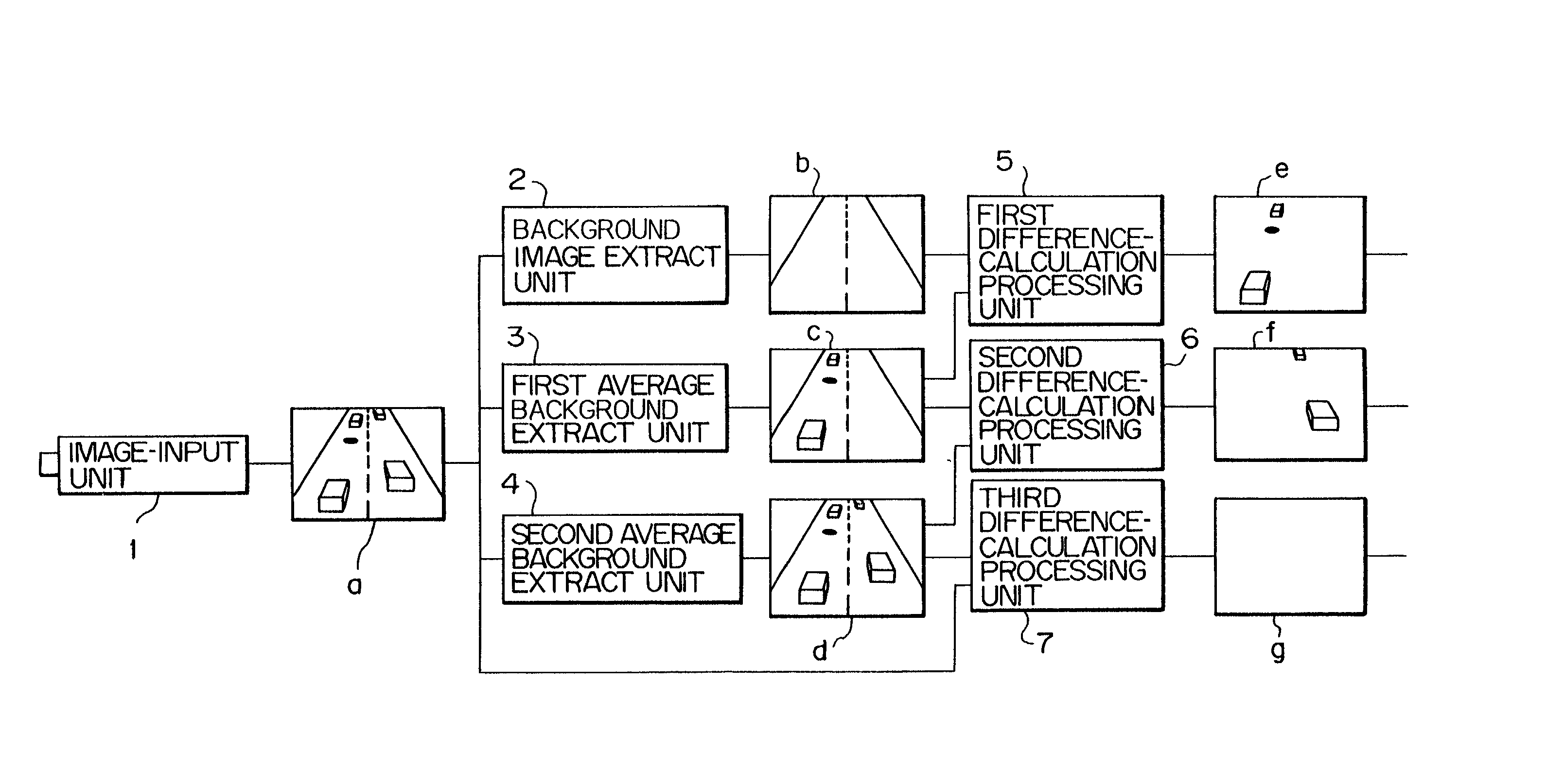
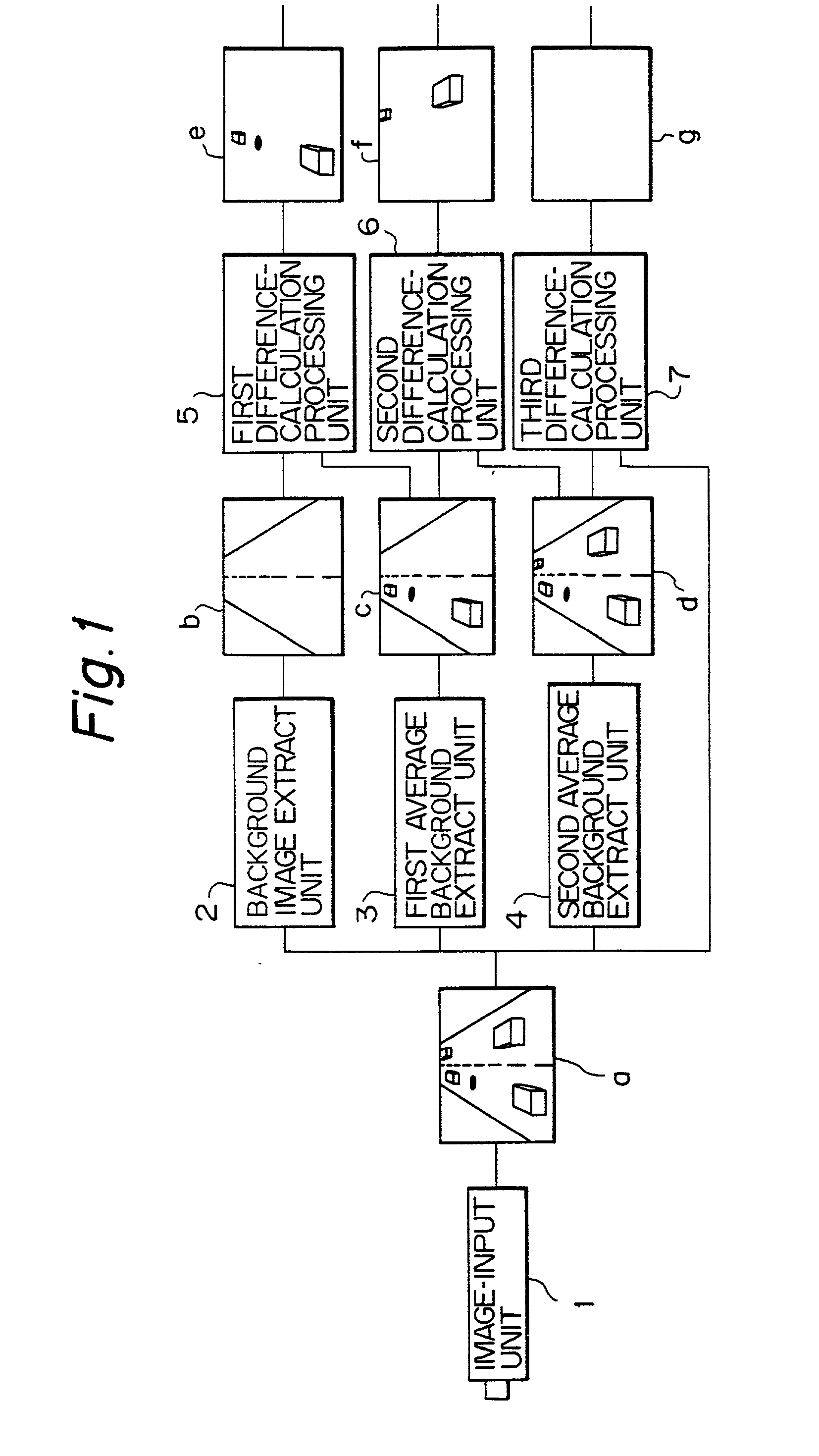
[0067] FIG. 1 is a schematic block diagram showing an essential embodiment based on the principal of the present invention. In FIG. 1, fundamental components necessary for realizing an image processing apparatus of the present invention are illustrated. In this case, it is assumed that a plurality of stationary objects (i.e., stopped objects) and a plurality of moving objects are contained together as a group of objects in an image which is to be processed.

[0068] As shown in FIG. 1, an image processing apparatus of the present invention includes an image-input unit 1, a background image extract unit 2, a first average background extract unit 3, a second average background extract unit 4, a first difference-calculation processing unit 5, a second difference-calculation processing unit 6, and a third difference-calculation processing unit 7.

[0069] More specifically, an image-input unit 1 is typically constituted by a video camera, and serves to input an image including a background an...


PUM


Abstract

An image processing apparatus for extracting the specified objects has a background image extract unit for extracting a background; a first average background extract unit which extracts an image that includes a plurality of stationary and moving objects each having a speed not higher than a predetermined first speed and also the background; a second average background extract unit which extracts an image that includes the stationary and moving objects each having a speed not higher than a predetermined second speed and also the background; a first difference-calculation processing unit which calculates a difference between an output from the background image extract unit and an output from the first average background extract unit as a first speed image; a second difference-calculation processing unit which calculates a difference value between two outputs from the first and second average background extract units as a second speed image; and a third difference-calculation processing unit which calculates a difference value between an original image and either one of outputs from the first and second average background extract units as a third speed image.

Description

BACKGROUND OF THE INVENTION[0001] 1. Field of the Invention[0002] The present invention relates to an image processing apparatus for accurately extracting one or a plurality of objects utilizing a thresholded differential image processing technique when a plurality of stationary objects and a plurality of moving objects are contained together in an image of a time sequence of images.[0003] More specifically, the present invention relates to an image processing apparatus, which allows both a background image and an image including at least one stationary object or at least one moving object (having a speed not more than a predetermined speed) to be extracted, and also allows a difference-calculation process to be carried out between the images.[0004] In such an image processing system, it is possible to distinguish a stationary object or a moving object in the images and it is also possible to analyze the movement of each of the moving objects.[0005] Further, the present invention re...

Claims


Application Information

Patent Timeline
IPC IPC(8): G06T7/20
CPCG06T7/254
Inventor NAOI, SATOSHIEGAWA, HIROICHISHIOHARA, MORITO
Owner FUJITSU LTD
Learn More