
Gas compressor

a compressor and gas technology, applied in the direction of machines/engines, liquid fuel engines, positive displacement liquid engines, etc., can solve the problems of increasing the overall cost of the overall compressor, and the difficulty of maintaining the constant oil separation function for a long period of time, so as to reduce the cost of the overall equipment, reduce the number of assembling steps, and high reliability

Inactive Publication Date: 2002-09-12
CALSONIC COMPRESSOR INC
View PDF0 Cites 4 Cited by
  • Summary
  • Abstract
  • Description
  • Claims
  • Application Information

AI Technical Summary

Benefits of technology

[0012] In order to attain the above-described problems, a first object of the present invention is to provide a gas compressor that is suitable for reducing cost for overall equipment while attaining the reduction of the numbers of assembling steps and the parts relating to the oil separator, and a second object thereof is to provide a gas compressor provided with an oil separator that is high in reliability to make it possible to keep a constant oil separation function that is needed for the compressor for a long period of time.

Problems solved by technology

Thus, there are many factors for increasing cost, resulting in increase in cost for the overall compressor.
That is, there is a problem in that it is difficult to keep the constant oil separation function for a long period time.

Method used


Image

  • Gas compressor
  • Gas compressor
  • Gas compressor

Examples


Embodiment Construction

[0038] An embodiment of a gas compressor according to the present invention will now be described with reference to FIGS. 1 to 10.

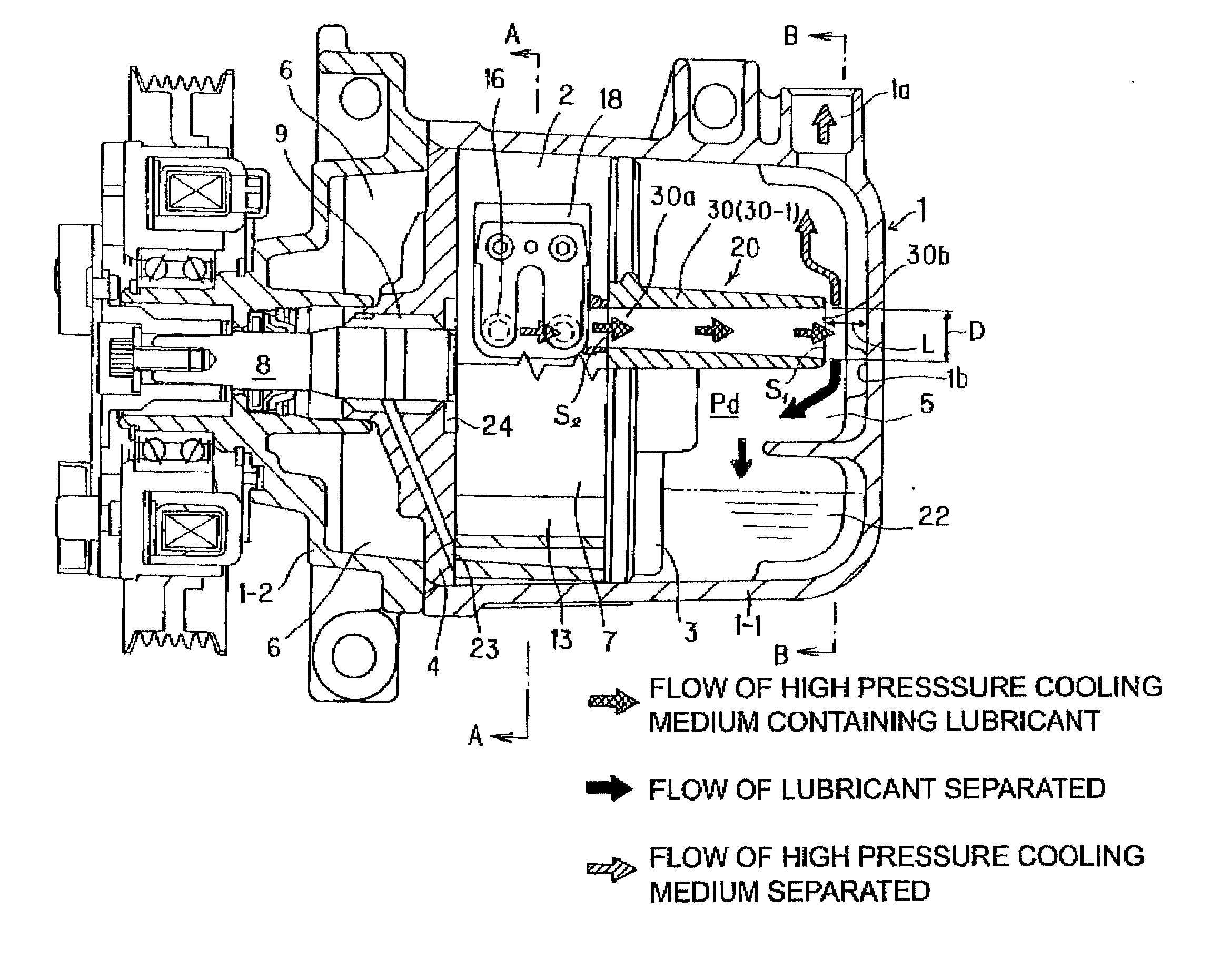
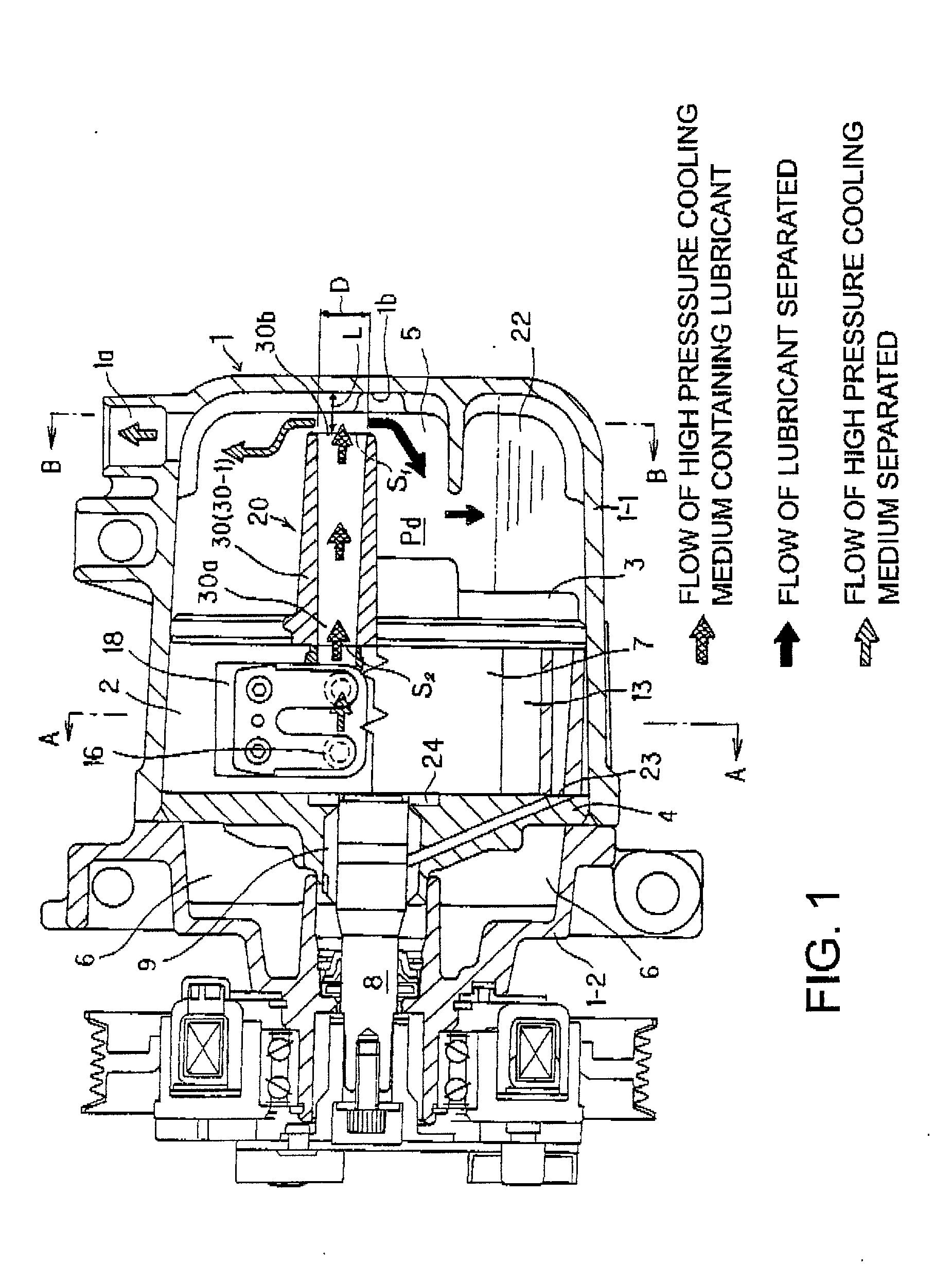
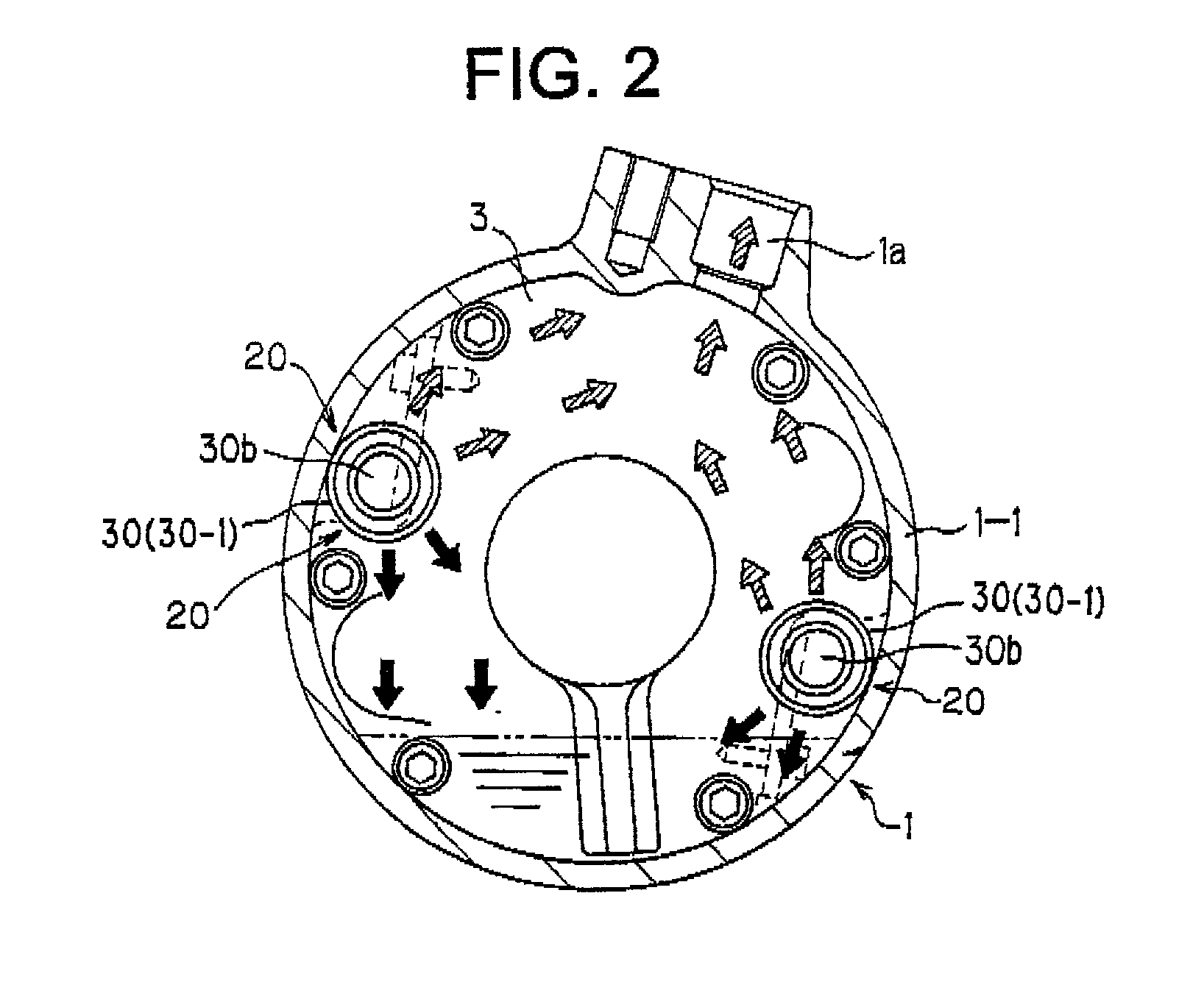
[0039] FIG. 1 is a cross-sectional view showing one embodiment of the gas compressor according to the present invention. The basic structure of this gas compressor such as the arrangement in which the cylinder 2 is disposed within the compressor case 1, the side blocks 3 and 4 are mounted at both end faces of the cylinder 2, and the second discharge chamber 5 is provided between one of the side blocks 3 and the inner sealed end of the compressor case 1 and the arrangement in which the high pressure cooling medium gas compressed in the compression chamber 13 within the cylinder 2 is discharged to the first discharge chamber 18 of the external space of the cylinder through the cylinder discharge port 16 and the like is the same as that of the conventional case. Accordingly, the same reference numerals are used to denote the same components and the detailed ...


PUM


Abstract

To provide a gas compressor that is suitable for reducing cost for the overall compressor without degrading the oil separation performance needed for the compressor and that may keep the oil separation performance constant for a long period of time. An oil separator having a pipe structure composed only of a discharge pipe formed integrally with a side block as a means for separating a lubricant oil component contained in high pressure cooling medium gas is adapted. In this case, the discharge pipe is adapted to form a discharge route for the high pressure cooling medium gas without any bypass immediately before an inner wall of a compressor case from a first discharge chamber. The separation of the lubricant oil component is performed by collision of the high pressure cooling medium gas, immediately after discharged from a cylinder discharge port to the first discharge chamber, against the inner wall of the compressor case through the discharge pipe without reducing a high flow rate.

Description

BACKGROUND OF THE INVENTION[0001] 2. Field of the Invention[0002] The present invention relates to a gas compressor assembled into an air-conditioning system for a vehicle or the like, and more particularly to a gas compressor in which it is possible to reduce a cost for the overall compressor without deteriorating its oil component separating function that is needed for the compressor, and to keep the oil component separating function constant for a long period of time.[0003] 2. Description of the Related Art[0004] In this kind of a conventional gas compressor, as shown in, for example, FIG. 11, a cylinder 2 having a substantially oval-shaped inner circumference is provided within a compressor case 1 and side blocks 3 and 4 are mounted at both end faces of the cylinder 2.[0005] In the case of the gas compressor of the same drawing, the compressor case 1 is formed of a box body 1-1 of one-end open type and a front head 1-2 mounted at the opening end thereof. A second discharge chamb...

Claims


Application Information

Patent Timeline
Patent Type & Authority Applications(United States)
IPC IPC(8): F01C21/10F04C18/344F04C29/02
CPCF01C21/10F04C18/3446F04C29/026Y10S418/01
Inventor MATSUURA, TOSHINARITOHYAMA, TATSUHIRO
Owner CALSONIC COMPRESSOR INC
Learn More