Method and apparatus for producing a prototype

Inactive Publication Date: 2002-09-19
MILLING SYST & CONCEPTS PTE
View PDF0 Cites 133 Cited by
  • Summary
  • Abstract
  • Description
  • Claims
  • Application Information

AI Technical Summary

Benefits of technology

0100] Process planning for optimal SFF system emphases a method of high speed and precision cutting on part held with support structure to which employing this method assures insignificant cutting force and minimum mechanical jerk to thereby avoid the migration of any parts from the support structure.
0101] To plan the feed rate and acceleration/deceleration of a system, the present invention employs the approach of off-line (planning done before feeding data to the SFF machine or computer control system) process planning. The reason is that operating on small/limited volume and high

Problems solved by technology

High performance solid freeform fabrication systems available in the market are still not affordable for the small or medium companies.
Also, the overhead

Method used


Image

  • Method and apparatus for producing a prototype
  • Method and apparatus for producing a prototype
  • Method and apparatus for producing a prototype

Examples


Embodiment Construction

[0111] The detail description of each factor in the system architecture of the optimal SFF system is presented below.

[0112] Process Steps:

[0113] To fabricate a 3D plastic or metal object of a predetermined shape, optimal SFF system adopts the GENERAL process steps illustrated in FIGS. 5a-5d.

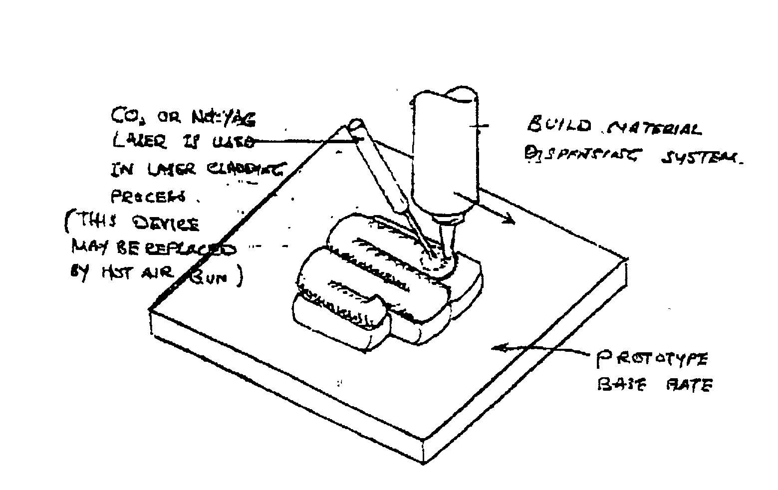
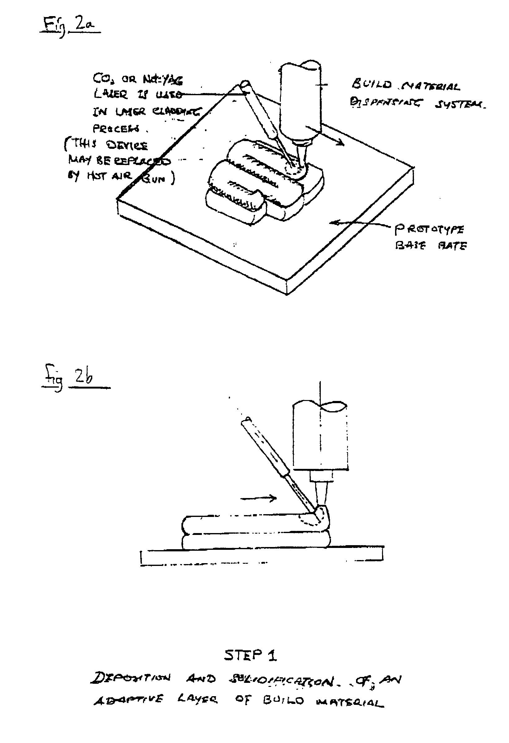
[0114] STEP 1: The first layer of build material is formed on the prototype base plate. The method of forming this layer is mostly dependent on the type of build material and build method used.

[0115] For instance, a plastic layer can be formed by dispensing wire-form plastic build materials incrementally with a plastic extruder. The material supplied to the plastic extruder can be in the form of filament or pellet. To have an appropriate control on the cutting and adhesion processes between the instantaneous and the previous wire-form plastic build materials, a focused or patch heating source, such as hot air, CO.sub.2 laser, infra-red light or Ultra-violet (UV) light (specifically for UV resin) ...


PUM

PropertyMeasurementUnit
Temperatureaaaaaaaaaa
Lengthaaaaaaaaaa
Shapeaaaaaaaaaa

Abstract

An apparatus for producing a prototype, the apparatus comprising a headstock having a plurality of machining apparatuses for carrying out respective manufacturing processes on a prototype. Also disclosed is a method of producing a prototype, comprising the steps of: forming a layer of the prototype; performing a machining process on the layer to remove a part of the layer, and subsequently forming a successive layer of the prototype on the layer of the prototype.

Description

[0001] This application claims the benefit of the filing date of U.S. Provisional Application No. 60 / 275,497 filed Mar. 13, 2001 and hereby incorporated by reference.[0002] This invention relates to one-off or small-volume production of three-dimensional items.BACKGROUND OF THE INVENTION[0003] The past decade had witnessed the emergence of several novel solid free-form fabrication (SFF) techniques that build 3D objects (prototypes) on layer-by-layer basis (additive process). These techniques shorten the manufacturing time of a 3D object virtually in any complexity to hours, instead of days or weeks.[0004] As compared to CNC machining, which frequently suffers from tool accessibility problems when matching complex parts, SFF technology's capable to build parts with deep slot, tight corner and undercut. Therefore, it is treated as an additional option in the functional part manufacturing toolkit.[0005] Currently, several SFF (or Rapid Prototyping) systems are now commercially availabl...

Claims


Application Information

Patent Timeline
IPC IPC(8): B23P17/00G05B19/00G05B19/4099
CPCG05B19/4099G05B2219/49017Y02P80/40B33Y10/00B29C64/106Y10T29/49982B29C64/118B29C64/188
Inventor MOK, STEVEN SIONG CHEAKCHONG, YEW HINGTOH, DA JUNBONG, TECK KEONG
Owner MILLING SYST & CONCEPTS PTE
Why Eureka
Try Eureka